Introduction
Follow this guide to replace, upgrade, or customzie the thumbstick covers (aka joystick covers) on your Steam Controller (2nd Gen, 2026).
Soldering is required to complete this repair. The capacitive touch wire for each thumbstick cap is soldered to the mainboard.
If you're new to soldering, check out our in-depth guide on soldering and desoldering connections.
If you suspect there's a problem with the thumbstick modules themselves, you may need to replace the main board (which the thumbsticks are soldered to). Check out this guide if you want to replace the main board.
What you need
-
-
Unplug all cables and accessories from the controller, including the Steam Controller Puck.
 Ask FixBot
-
-
Tool used on this step:TR6 Torx Security Screwdriver$5.99
-
Use a T6 Torx screwdriver to remove the seven screws securing the back cover.
-
Throughout this repair, keep track of each screw and make sure it goes back exactly where it came from.
-
-
-
Use a T6 Torx screwdriver to remove the four 7.4 mm‑long screws securing the battery mounting bracket.
-
-
-
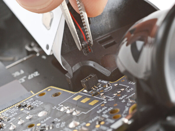
Firmly grip the short edges of one rumble motor connector with a pair of tweezers and pull straight up to disconnect it
-
-
-
-
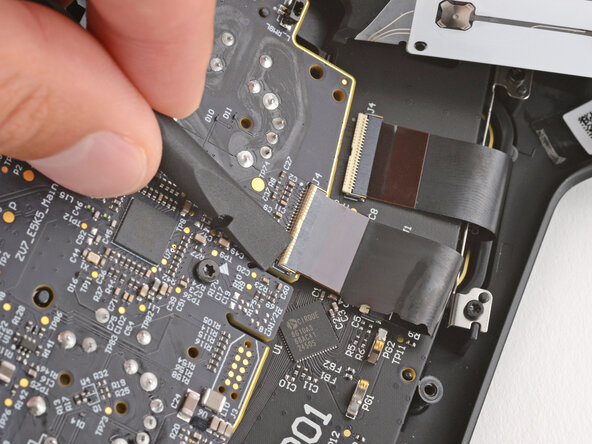
Use a spudger to lift the hinged locking flap on the interconnect cable ZIF connector, located on the bottom edge of the main board.
-
-
-
Use tweezers to grip the cable by its plastic pull tab and slide it out of the socket.
-
-
-
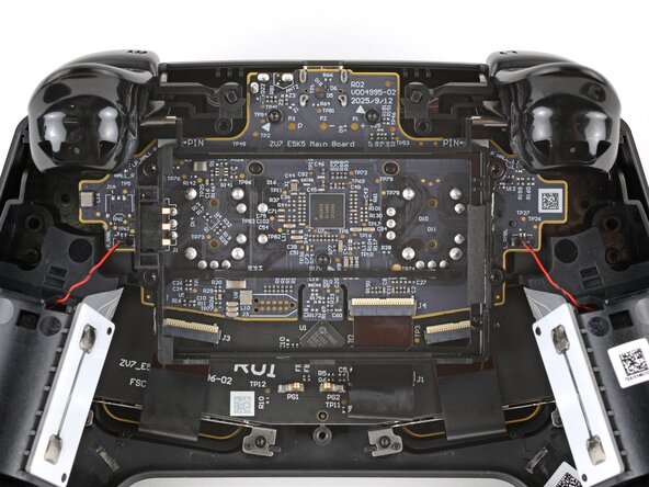
Use a T6 Torx screwdriver to remove the three 7.4 mm‑long screws securing the main board.
-
-
-
Pull the main board down so the top corners clear the triggers.
-
Remove the main board, guiding the thumbsticks through their cutouts.
-
-
-
If the rubber piece is out of place, remove it and set it aside.
-
-
-
Hold the mainboard steady and firmly lift both thumstick covers straight up to separate them from their modules.
-
-
-
The solder joints for the capacitive touch wires are both covered with a dab of clear, protective glue.
-
Use a heat gun or hair dryer to heat each pad until it becomes soft.
-
Use pointed tweezers to slowly peel up and remove both dabs of glue.
-
-
-
If your soldering iron has a temperature setting, set it to 350 °C (~650 °F).
-
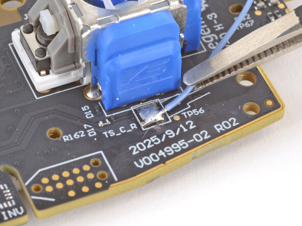
Use tweezers to grip one of the capacitive touch wires close to its solder connection.
-
Press the tip of your iron against the solder connection until it melts, then lift the wire away with the tweezers.
-
-
-
Heat the pad with your iron and feed a small amount of solder onto the pad to form a bead.
-
-
-
Use tweezers to hold the replacement thumbstick cover's capacitive touch wire on the solder bead, so the wire is facing the direction shown in the diagram on the board.
-
Press the tip of your iron onto the bead until it melts, making sure the wire gets covered with solder for a solid connection.
-
Repeat the last two steps to solder the second capacitive touch wire.
-


To reassemble your device, follow these instructions in reverse order starting with this step.
Take your e-waste to an R2 or e-Stewards certified recycler.
Repair didn’t go as planned? Try some basic troubleshooting, or ask our Answers community for help.
Cancel: I did not complete this guide.
One other person completed this guide.
