Free Shipping on Domestic Orders $75+

Framework Laptop 13 Mainboard Replacement

What you need

  1. Framework Laptop 13 Mainboard Replacement, Before you begin: step 1, image 1 of 2 Framework Laptop 13 Mainboard Replacement, Before you begin: step 1, image 2 of 2
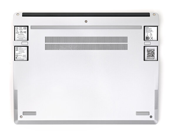
    • Unplug all cables and fully shut down your laptop from the OS.

  2. Framework Laptop 13 Mainboard Replacement, Remove the Expansion Cards: step 2, image 1 of 2 Framework Laptop 13 Mainboard Replacement, Remove the Expansion Cards: step 2, image 2 of 2
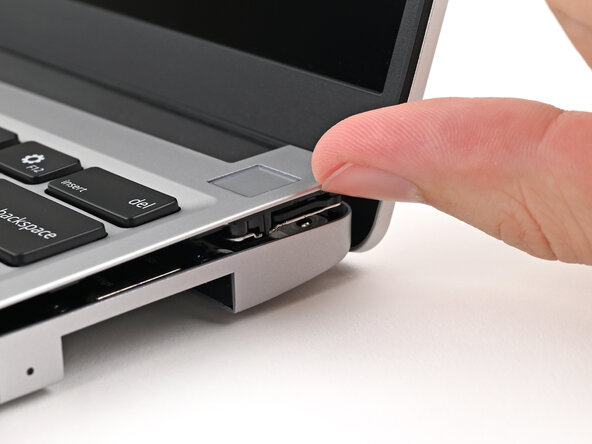
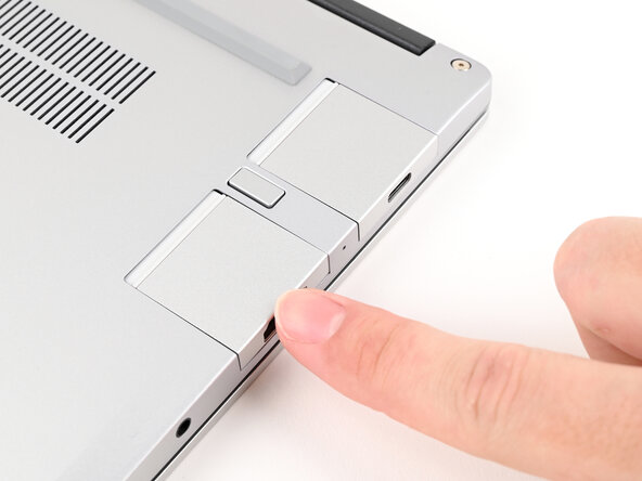
    • While pressing down the release button, grip the lip of the Expansion Card and pull it out of its slot to release it.

    • This might take some initial force. If you're having trouble, make sure you're fully pressing down the release button.

  3. Framework Laptop 13 Mainboard Replacement: step 3, image 1 of 2 Framework Laptop 13 Mainboard Replacement: step 3, image 2 of 2
    • Slide the Expansion Card out of its slot and remove it.

    • Remove the remaining Expansion Cards.

  4. Framework Laptop 13 Mainboard Replacement, Loosen the Input Cover screws: step 4, image 1 of 2 Framework Laptop 13 Mainboard Replacement, Loosen the Input Cover screws: step 4, image 2 of 2
    • Use your Framework Screwdriver to loosen the five captive T5 Torx screws securing the Input Cover.

    • The screw will make an audible "clicking" sound once it's fully loosened.

  5. Framework Laptop 13 Mainboard Replacement, Lift the Input Cover: step 5, image 1 of 2 Framework Laptop 13 Mainboard Replacement, Lift the Input Cover: step 5, image 2 of 2
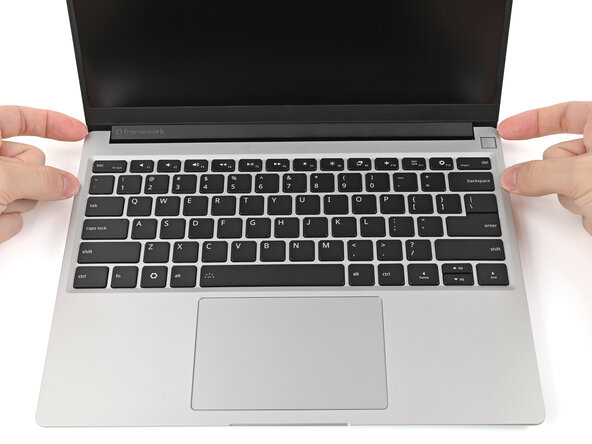
    • Open the laptop.

    • Use your fingers to lift the Input Cover up and release it from its magnets.

    • Don't fully remove the Input Cover yet, as it's still attached by the Touchpad Cable.

    • If you're having trouble lifting the Input Cover, you can leverage the gap at the bottom right corner to get your fingers fully under it.

  6. Framework Laptop 13 Mainboard Replacement, Flip over the Input Cover: step 6, image 1 of 2 Framework Laptop 13 Mainboard Replacement, Flip over the Input Cover: step 6, image 2 of 2
    • Flip the top of the Input Cover so the keyboard is facing down.

    • Rest the Input Cover over the Battery, making sure the Touchpad Cable isn't being strained.

    • If the LEDs on the left and right sides of the Mainboard are flashing, then your laptop is still powered on. Make sure your laptop is completely powered off before continuing.

  7. Framework Laptop 13 Mainboard Replacement, Disconnect the Touchpad Cable: step 7, image 1 of 2 Framework Laptop 13 Mainboard Replacement, Disconnect the Touchpad Cable: step 7, image 2 of 2
    • Insert your finger into the Touchpad Cable press connector loop.

    • Lift up to disconnect the Touchpad Cable from the Mainboard.

  8. Framework Laptop 13 Mainboard Replacement, Remove the Input Cover: step 8, image 1 of 2 Framework Laptop 13 Mainboard Replacement, Remove the Input Cover: step 8, image 2 of 2
    • Remove the Input Cover.

  9. Framework Laptop 13 Mainboard Replacement, Disconnect the Battery: step 9, image 1 of 2 Framework Laptop 13 Mainboard Replacement, Disconnect the Battery: step 9, image 2 of 2
    • When disconnecting the Battery, make sure you slide its connector straight out of its socket or else you risk bending the socket's pins.

    • Use your fingers to grip the edges of the Battery connector and slide it straight out of its socket to disconnect the Battery.

  10. Framework Laptop 13 Mainboard Replacement, Remove the memory: step 10, image 1 of 3 Framework Laptop 13 Mainboard Replacement, Remove the memory: step 10, image 2 of 3 Framework Laptop 13 Mainboard Replacement, Remove the memory: step 10, image 3 of 3
    • Depending on your Mainboard's generation, you might not have black flaps covering your memory.

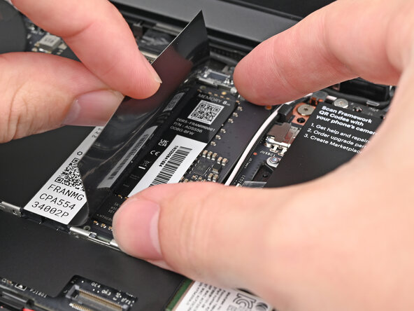
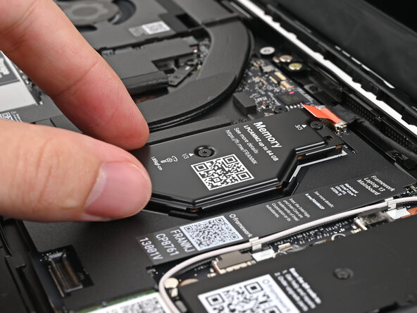
    • While holding up the black flap covering the left memory module, push the two metal arms on each side of the module outward until they disengage and the module pops up at a shallow angle.

    • Slide the memory module out of its socket and remove it.

  11. Framework Laptop 13 Mainboard Replacement: step 11, image 1 of 3 Framework Laptop 13 Mainboard Replacement: step 11, image 2 of 3 Framework Laptop 13 Mainboard Replacement: step 11, image 3 of 3
    • Repeat the previous step for the right module.

  12. Framework Laptop 13 Mainboard Replacement, Remove the SSD screw: step 12, image 1 of 2 Framework Laptop 13 Mainboard Replacement, Remove the SSD screw: step 12, image 2 of 2
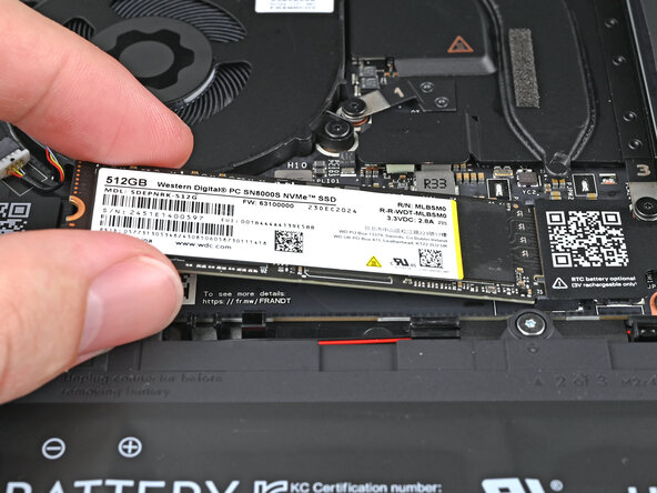
    • Use your Framework Screwdriver to remove the 3.0 mm‑long T5 Torx screw securing the SSD.

    • The SSD might pop up at a shallow angle when you remove the screw.

  13. Framework Laptop 13 Mainboard Replacement, Remove the SSD: step 13, image 1 of 2 Framework Laptop 13 Mainboard Replacement, Remove the SSD: step 13, image 2 of 2
    • Grip the end of the SSD with the screw hole and slide it out of its socket.

    • Remove the SSD.

  14. Framework Laptop 13 Mainboard Replacement, Disconnect the speaker: step 14, image 1 of 2 Framework Laptop 13 Mainboard Replacement, Disconnect the speaker: step 14, image 2 of 2
    • Use your fingers to grip the edges of the speaker cable connector.

    • Pull the connector straight out of its socket to disconnect it.

  15. Framework Laptop 13 Mainboard Replacement, Disconnect the Audio Board: step 15, image 1 of 2 Framework Laptop 13 Mainboard Replacement, Disconnect the Audio Board: step 15, image 2 of 2
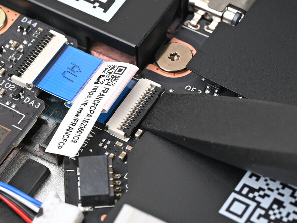
    • Use the flat end of your Framework Screwdriver, or a clean fingernail, to lift up the locking tab on the Audio Board ZIF connector on the Mainboard.

  16. Framework Laptop 13 Mainboard Replacement: step 16, image 1 of 2 Framework Laptop 13 Mainboard Replacement: step 16, image 2 of 2
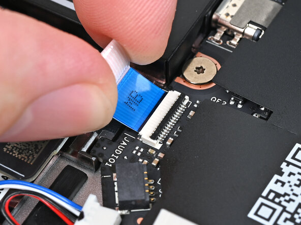
    • Use your fingers to lightly grip the Audio Board cable and slide it straight out of its socket.

  17. Framework Laptop 13 Mainboard Replacement, Disconnect the eDP Cable: step 17, image 1 of 2 Framework Laptop 13 Mainboard Replacement, Disconnect the eDP Cable: step 17, image 2 of 2
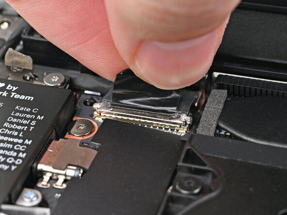
    • Grip the eDP Cable connector by its pull tab and lift up to disconnect it.

  18. Framework Laptop 13 Mainboard Replacement, Disconnect the Webcam Cable: step 18, image 1 of 2 Framework Laptop 13 Mainboard Replacement, Disconnect the Webcam Cable: step 18, image 2 of 2
    • Repeat the previous step for the Webcam Cable connector.

  19. Framework Laptop 13 Mainboard Replacement, Lift the antenna cables: step 19, image 1 of 3 Framework Laptop 13 Mainboard Replacement, Lift the antenna cables: step 19, image 2 of 3 Framework Laptop 13 Mainboard Replacement, Lift the antenna cables: step 19, image 3 of 3
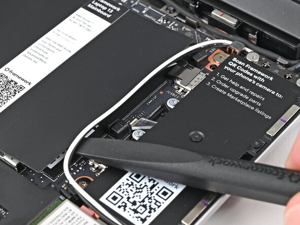
    • Use the flat end of the Framework Screwdriver to lift the two antenna cables out of their rubber clips on the Mainboard.

  20. Framework Laptop 13 Mainboard Replacement, Loosen the Wi-Fi module screw: step 20, image 1 of 2 Framework Laptop 13 Mainboard Replacement, Loosen the Wi-Fi module screw: step 20, image 2 of 2
    • Use your Framework Screwdriver to loosen the captive T5 Torx screw securing Wi-Fi module.

    • The module might pop up at a shallow angle when you loosen the screw.

  21. Framework Laptop 13 Mainboard Replacement, Disconnect the Wi-Fi module: step 21, image 1 of 3 Framework Laptop 13 Mainboard Replacement, Disconnect the Wi-Fi module: step 21, image 2 of 3 Framework Laptop 13 Mainboard Replacement, Disconnect the Wi-Fi module: step 21, image 3 of 3
    • Grip the end of the Wi-Fi module with the screw hole and slide it out of its socket.

    • Don't pull the module too far from its socket, as it's still connected by two cables.

    • Keep the plastic bracket attached to the module to prevent the cables from disconnecting.

    • Position the Wi-Fi module to the right of the laptop to keep it out of the way of the Mainboard.

  22. Framework Laptop 13 Mainboard Replacement, Remove the Mainboard screws: step 22, image 1 of 2 Framework Laptop 13 Mainboard Replacement, Remove the Mainboard screws: step 22, image 2 of 2
    • Use your Framework Screwdriver to remove the five 1.5 mm‑long T5 Torx screws securing the Mainboard.

    • Since these screws aren't captive, put them in a safe place.

  23. Framework Laptop 13 Mainboard Replacement, Remove the Mainboard: step 23, image 1 of 3 Framework Laptop 13 Mainboard Replacement, Remove the Mainboard: step 23, image 2 of 3 Framework Laptop 13 Mainboard Replacement, Remove the Mainboard: step 23, image 3 of 3
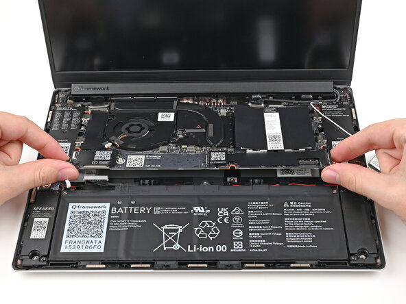
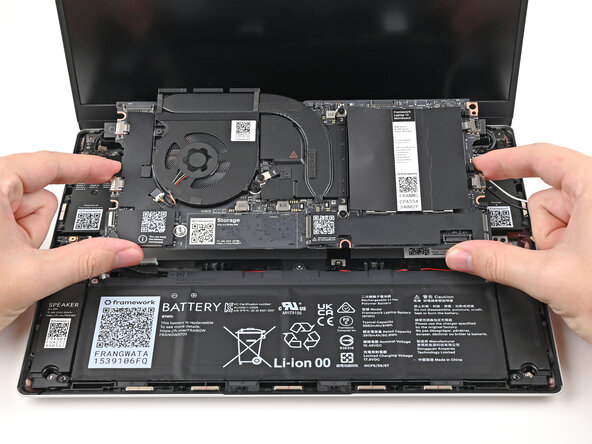
    • Use your fingers to lift the bottom edge of the Mainboard enough to grip its edges.

    • Lift the Mainboard off its alignment pegs and remove it.

  24. Framework Laptop 13 Mainboard Replacement, Disassembly complete: step 24, image 1 of 1
    • Congratulations on completing disassembly! The remaining steps will show how to reassemble your Framework Laptop.

  25. Framework Laptop 13 Mainboard Replacement, Place the Mainboard: step 25, image 1 of 2 Framework Laptop 13 Mainboard Replacement, Place the Mainboard: step 25, image 2 of 2
    • Grab the Mainboard by its edges and place it into the laptop and onto its alignment pegs.

    • Make sure all of the cables are above the Mainboard before continuing. Refer to this image for where the cables are located.

  26. Framework Laptop 13 Mainboard Replacement, Install the Mainboard screws: step 26, image 1 of 2 Framework Laptop 13 Mainboard Replacement, Install the Mainboard screws: step 26, image 2 of 2
    • Use your Framework Screwdriver to install the five 1.5 mm‑long T5 Torx screws securing the Mainboard.

  27. Framework Laptop 13 Mainboard Replacement, Connect the Webcam Cable: step 27, image 1 of 2 Framework Laptop 13 Mainboard Replacement, Connect the Webcam Cable: step 27, image 2 of 2
    • Press the Webcam Cable connector straight down into its socket to connect it.

  28. Framework Laptop 13 Mainboard Replacement, Connect the eDP Cable: step 28, image 1 of 2 Framework Laptop 13 Mainboard Replacement, Connect the eDP Cable: step 28, image 2 of 2
    • Repeat the previous step for the eDP Cable.

  29. Framework Laptop 13 Mainboard Replacement, Install the Wi-Fi module: step 29, image 1 of 2 Framework Laptop 13 Mainboard Replacement, Install the Wi-Fi module: step 29, image 2 of 2
    • Hold the Wi-Fi module by its edges. Don't touch the gold contacts with your fingers. If you do, wipe the contacts with a clean, lint-free cloth to remove any finger oils.

    • Align the Wi-Fi module's gold contacts and notch with the socket on the Mainboard.

    • Insert the Wi-Fi module into the socket at a shallow angle. The gold contacts should mostly be covered by the socket.

    • The Wi-Fi module fits into the socket in one orientation. If it doesn't fit, try flipping the module.

  30. Framework Laptop 13 Mainboard Replacement, Reconnect the Wi-Fi module: step 30, image 1 of 3 Framework Laptop 13 Mainboard Replacement, Reconnect the Wi-Fi module: step 30, image 2 of 3 Framework Laptop 13 Mainboard Replacement, Reconnect the Wi-Fi module: step 30, image 3 of 3
    • If the antenna cables got accidentally disconnected, follow this step to reconnect them. Otherwise, skip this step to continue the guide normally.

    • Hold the Wi-Fi module down with your finger.

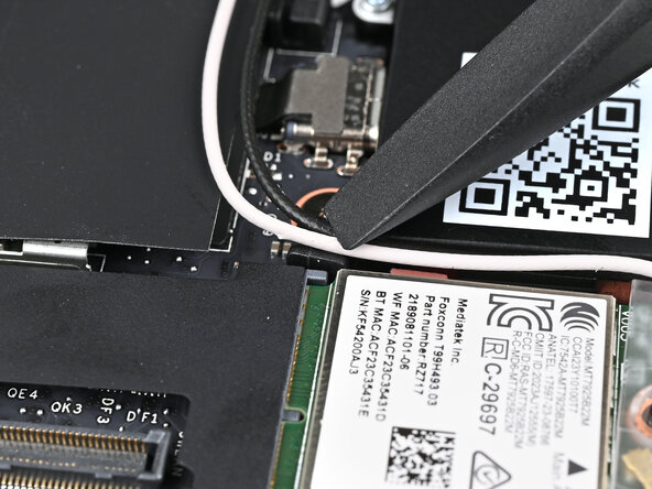
    • Position the black antenna cable connector over the left Wi-Fi module's coaxial socket.

    • If you're unsure which cable goes where, refer to the arrows on the Wi-Fi module for which color cable matches with its connector.

    • Tweezers can help position the connector.

    • Use your finger to press the connector into place. You should feel a faint click, and the cable will stay attached to the socket by itself.

    • These connectors are very delicate! If the connector doesn't feel like it's clicking in place, reposition the connector and try again.

    • Repeat the procedure with the white antenna cable.

  31. Framework Laptop 13 Mainboard Replacement, Tighten the Wi-Fi Module screw: step 31, image 1 of 2 Framework Laptop 13 Mainboard Replacement, Tighten the Wi-Fi Module screw: step 31, image 2 of 2
    • Use your Framework Screwdriver to tighten the captive T5 Torx screw securing Wi-Fi module.

  32. Framework Laptop 13 Mainboard Replacement, Reroute the antenna cables: step 32, image 1 of 3 Framework Laptop 13 Mainboard Replacement, Reroute the antenna cables: step 32, image 2 of 3 Framework Laptop 13 Mainboard Replacement, Reroute the antenna cables: step 32, image 3 of 3
    • Use the flat end of your Framework Screwdriver to press the two antenna cables into their rubber clips on the Mainboard.

  33. Framework Laptop 13 Mainboard Replacement, Connect the Audio Board: step 33, image 1 of 2 Framework Laptop 13 Mainboard Replacement, Connect the Audio Board: step 33, image 2 of 2
    • Slide the Audio Board cable straight into its socket.

  34. Framework Laptop 13 Mainboard Replacement: step 34, image 1 of 2 Framework Laptop 13 Mainboard Replacement: step 34, image 2 of 2
    • Use the flat end of your Framework Screwdriver, or a clean fingernail, to press down the locking tab on the Audio Board ZIF connector.

  35. Framework Laptop 13 Mainboard Replacement, Connect the speakers: step 35, image 1 of 2 Framework Laptop 13 Mainboard Replacement, Connect the speakers: step 35, image 2 of 2
    • Slide the speaker connector straight into its socket.

  36. Framework Laptop 13 Mainboard Replacement, Install the SSD: step 36, image 1 of 2 Framework Laptop 13 Mainboard Replacement, Install the SSD: step 36, image 2 of 2
    • Hold the SSD by its edges. Don't touch the gold contacts with your fingers. If you do, wipe the contacts with a clean, lint-free cloth to remove any finger oils.

    • Insert the SSD into the socket at a shallow angle. The gold contacts should mostly be covered by the socket.

    • The SSD fits into the socket in one orientation. If it doesn't feel like it fits, try flipping the module.

  37. Framework Laptop 13 Mainboard Replacement: step 37, image 1 of 2 Framework Laptop 13 Mainboard Replacement: step 37, image 2 of 2
    • While holding the SSD flat to the Mainboard, use your Framework Screwdriver to install the 3.0 mm‑long T5 Torx screw securing the SSD.

  38. Framework Laptop 13 Mainboard Replacement, Install the left memory: step 38, image 1 of 3 Framework Laptop 13 Mainboard Replacement, Install the left memory: step 38, image 2 of 3 Framework Laptop 13 Mainboard Replacement, Install the left memory: step 38, image 3 of 3
    • Hold the memory module by its edges. Don't touch the gold contacts with your fingers. If you do, wipe the contacts with a clean, lint-free cloth to remove any finger oils.

    • While holding up the black flap covering the left memory module, orient the module with its label facing down and align the gold contacts with the left socket.

    • Insert the contact edge into the socket at a shallow angle. The gold contacts should mostly be covered by the socket.

    • Press the edges of the module down until the side clips lock it in place.

  39. Framework Laptop 13 Mainboard Replacement, Install the right memory: step 39, image 1 of 3 Framework Laptop 13 Mainboard Replacement, Install the right memory: step 39, image 2 of 3 Framework Laptop 13 Mainboard Replacement, Install the right memory: step 39, image 3 of 3
    • Repeat the previous step for the right socket, except orient the module so its label is facing upward.

  40. Framework Laptop 13 Mainboard Replacement, Check the battery socket: step 40, image 1 of 2 Framework Laptop 13 Mainboard Replacement, Check the battery socket: step 40, image 2 of 2
    • Before continuing, check the pins on the battery socket and make sure they aren't bent.

    • If any of the pins are bent, reach out to Framework Support.

  41. Framework Laptop 13 Mainboard Replacement, Reconnect the battery: step 41, image 1 of 3 Framework Laptop 13 Mainboard Replacement, Reconnect the battery: step 41, image 2 of 3 Framework Laptop 13 Mainboard Replacement, Reconnect the battery: step 41, image 3 of 3
    • Use your fingers to align the battery connector with its socket and slide it straight in to reconnect the battery.

  42. Framework Laptop 13 Mainboard Replacement, Check the Touchpad Cable: step 42, image 1 of 3 Framework Laptop 13 Mainboard Replacement, Check the Touchpad Cable: step 42, image 2 of 3 Framework Laptop 13 Mainboard Replacement, Check the Touchpad Cable: step 42, image 3 of 3
    • Before continuing, check the Touchpad Cable's ZIF connector located on the back of the Touchpad:

    • Make sure the white line on the cable is parallel to and adjacent with the socket.

    • If the cable isn't inserted far enough, use the flat end of the Framework Screwdriver to flip up the black latch, reposition the cable, and lock the latch.

  43. Framework Laptop 13 Mainboard Replacement, Position the Input Cover: step 43, image 1 of 2 Framework Laptop 13 Mainboard Replacement, Position the Input Cover: step 43, image 2 of 2
    • Position the Input Cover, keyboard down, on top of the laptop so it just covers the battery.

    • This allows the Touchpad Cable to be folded over and reconnected without straining it.

  44. Framework Laptop 13 Mainboard Replacement, Connect the Touchpad Cable: step 44, image 1 of 2 Framework Laptop 13 Mainboard Replacement, Connect the Touchpad Cable: step 44, image 2 of 2
    • Insert your finger into the Touchpad Cable press connector loop.

    • Align the press connector over its socket and press down with your finger.

    • You should hear it "click" into place. Don't try to force the connector into place. If you're having trouble, reposition it and try again.

  45. Framework Laptop 13 Mainboard Replacement, Place the Input Cover: step 45, image 1 of 2 Framework Laptop 13 Mainboard Replacement, Place the Input Cover: step 45, image 2 of 2
    • Flip the Input Cover over the laptop and align the bottom edges.

  46. Framework Laptop 13 Mainboard Replacement: step 46, image 1 of 3 Framework Laptop 13 Mainboard Replacement: step 46, image 2 of 3 Framework Laptop 13 Mainboard Replacement: step 46, image 3 of 3
    • Lay the Input Cover over the laptop and let the magnets snap it into place.

    • The bottom right corner of the Input Cover won't sit flush with the laptop until you tighten its screws.

  47. Framework Laptop 13 Mainboard Replacement, Tighten the Input Cover screws: step 47, image 1 of 2 Framework Laptop 13 Mainboard Replacement, Tighten the Input Cover screws: step 47, image 2 of 2
    • Use your Framework Screwdriver to tighten the five captive T5 Torx screws securing the Input Cover.

    • Don't overtighten the screws—just make sure they're snug.

  48. Framework Laptop 13 Mainboard Replacement, Install the Expansion Cards: step 48, image 1 of 3 Framework Laptop 13 Mainboard Replacement, Install the Expansion Cards: step 48, image 2 of 3 Framework Laptop 13 Mainboard Replacement, Install the Expansion Cards: step 48, image 3 of 3
    • Slide an Expansion Card into an Expansion Card slot.

    • You don't need to hold down the release button to install the Expansion Cards—only when you want to remove them.

    • The Expansion Cards should click into place, and the front edge should be flush with the laptop.

    • For Expansion Card compatibility, check here.

    • Repeat for the remaining Expansion Cards.

Conclusion

You finished fixing your Framework Laptop!

Take your e-waste to an R2 or e-Stewards certified recycler.

If you need help, contact Framework support.

Alex Diaz-Kokaisl

Member since: 01/16/22

237,575 Reputation

1,171 Guides authored

0 Guide Comments

Add Comment

View Statistics:

Past 24 Hours: 6

Past 7 Days: 25

Past 30 Days: 160

All Time: 284