
Abask J05 Camera Replacement

Valerie Kulnar and 3 other contributors
Last updated on Dec 18, 2023
Views: 469
View statistics:
- Past 24 Hours:
- 2
- Past 7 Days:
- 13
- Past 30 Days:
- 64
- All Time:
- 469
Comments: 0
No one has left comments on this guide. Will you be first?
Go to guide commentsCompleted: 1 2
1 person has marked this guide "completed." Will you be next?
2 people have marked this guide "completed." Including you — great job!
Favorites: 0 1
No one has favorited (and subscribed to) this guide. Will you be the first?
1 person has favorited (and subscribed to) this guide — and that's you!
Introduction
Go to step 1 ↓This is a step-by-step guide to replace the front camera of your Abask J05 dashcam.
The camera captures at 30 FPS at 1080p with a 170° wide angle design. Its function is to capture video footage while the owner is driving in order to provide reliable evidence in cases such as car crashes. If your device's recordings are obscured, distorted, or blank, it may be in need of replacement. Before replacing any components of your device, be sure to check the troubleshooting guide, as there may be reasons your camera isn't functioning that don't require replacement.
What you need
Tools


-
-
-
Gently press on the SD card with a fingernail until it clicks.
-
Release, then remove the card.
 Ask FixBot
-
-
-
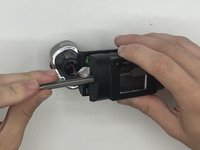
Remove the 5 mm screw from the side of the device next to the suction cup dock with a Phillips #00 screwdriver.
-
-
-
Remove the two 8 mm screws from opposite sides of the screen with a Phillips #00 precision screwdriver.
-
-
-
Gently lift the screen.
-
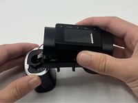
Push up on the interior camera portion of the device. It should pop out of the socket. Being careful to keep the wires attached, set it to the side.
-
-
-
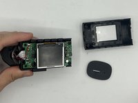
Reach into the device with a spudger to release the top two snap joints keeping the end cap attached one at a time until the front face lifts off.
-
Repeat the process with the two remaining snap joints.
-
-
-
-
-
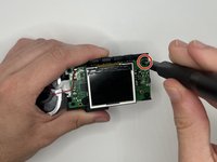
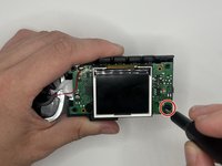
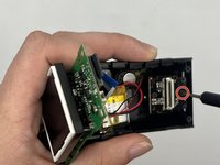
Remove the two 7 mm screws on the side of the motherboard with a Phillips #00 screwdriver.
-
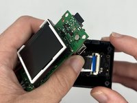
Slowly pull up on each corner of the motherboard, stopping when the corner pops loose of the anchor.
-
Repeat the process with each corner before slowly pulling up on the board to detach the glue on the underside.
-
-
-
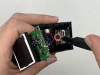
Move the motherboard aside, and peel off the tape over the small black plastic piece.
-
-
-


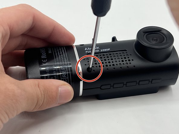
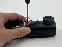
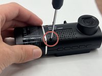


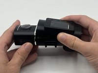












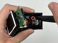
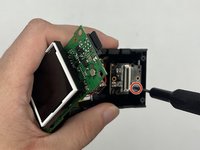


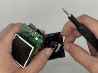
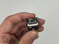
To reassemble your device, follow these instructions in reverse order. (Note: When doing the steps in reverse order, do not do Step 5. Instead, place the front face of the device back on the main body before lining up the endcap, ensuring proper orientation with the SD card slot, and push in until you hear all four snap joints snap into place.)
Cancel: I did not complete this guide.
One other person completed this guide.

Team

University of North Texas, Team 2-2, Harold Fall 2023 Member of University of North Texas, Team 2-2, Harold Fall 2023
UNT-HAROLD-F23S2G2
4 Members
60 Guides authored
