Introduction
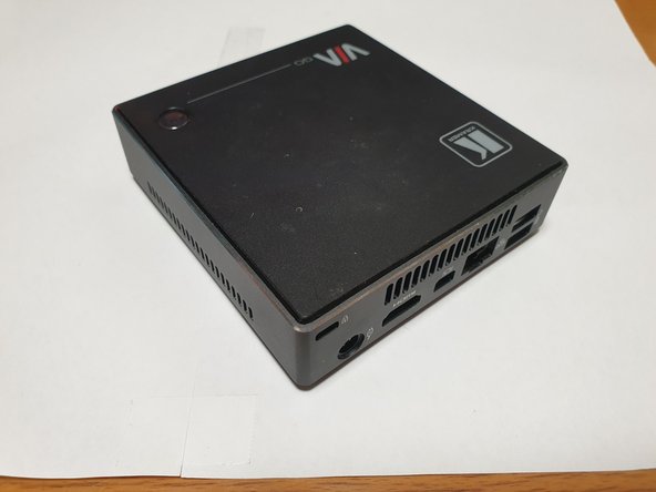
Explore internals of the device: layout, components and upgradability.
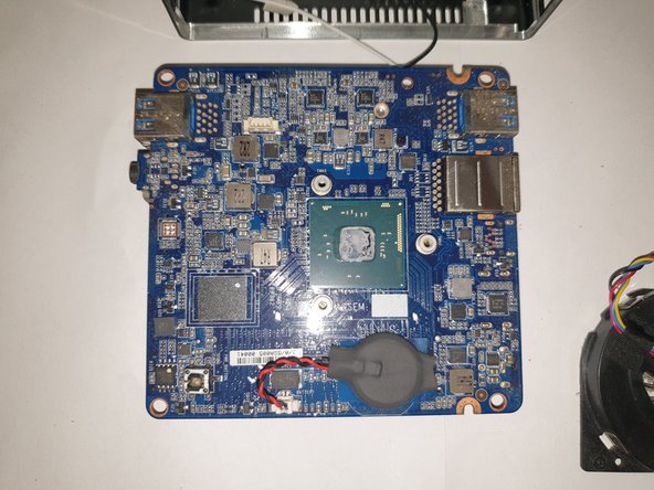
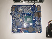
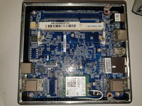
GIGABYTE VIA-GO motherboard, model MZBSWOP-W1
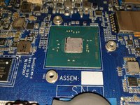
Intel Celeron N3010 (cpuid 406C4)
LPDDR3 1.35V SODIMM
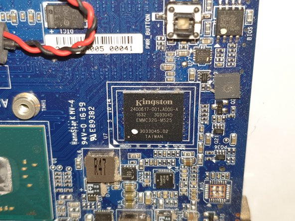
integrated eMMC (SD) Kingston M52532 1AED76C6 32Gb
-
-
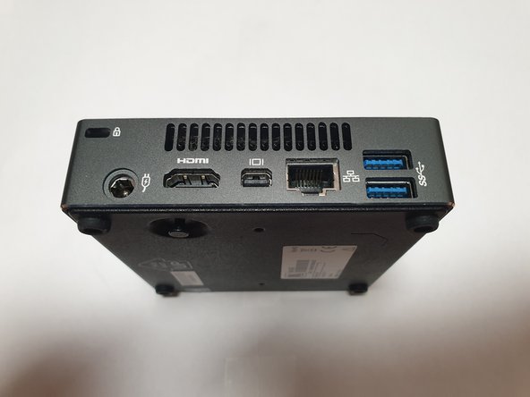
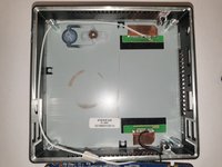
Remove four (phillips) screws on the bottom of the device, these are located inside of rubber feet.
-
-
-
-
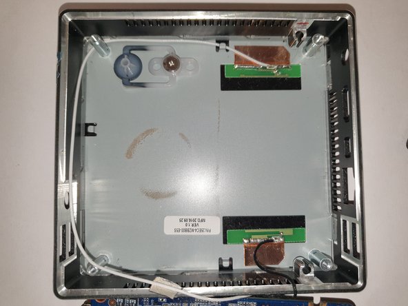
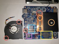
remove screws that hold motherboard in the case.
-
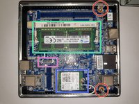
LPDDR3 slot (there is no internal memory).
-
M.2 slot with Intel 3160NGW (Dual-band AC-WiFi + BT)
-
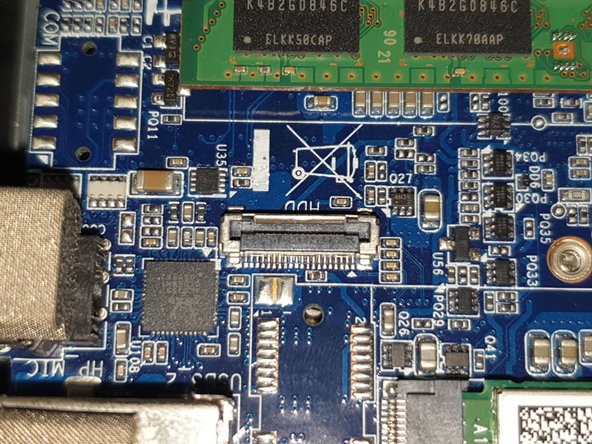
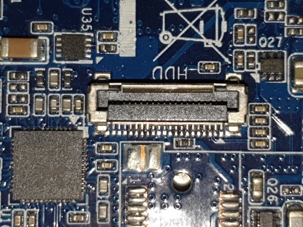
20-pin connector for external SATA hard drive.
-
-
-
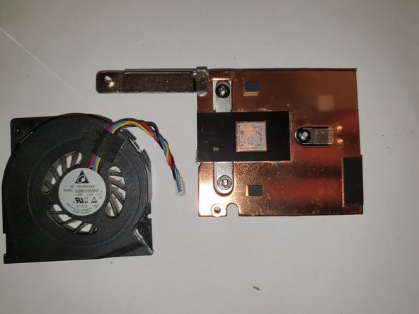
screws to remove fan assembly
-
screws to remove heatsink
-
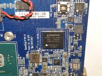
RTC battery
-
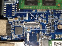
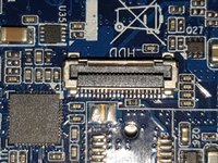
eMMC (SD) chip
-
power button
-