Free Shipping on Domestic Orders $75+

What you need

This teardown is not a repair guide. To repair your GV30, use our service manual.

  1. GV30 Teardown, GV30 Teardown: step 1, image 1 of 1
    • Unscrew the screws on the back side

    Ask FixBot

    Add Comment

  2. GV30 Teardown: step 2, image 1 of 2 GV30 Teardown: step 2, image 2 of 2
    • Move the microusb port to release the circuit

    Ask FixBot

    Add Comment

  3. GV30 Teardown: step 3, image 1 of 3 GV30 Teardown: step 3, image 2 of 3 GV30 Teardown: step 3, image 3 of 3
    • The cables don't consent to separate the parts

    Ask FixBot

    Add Comment

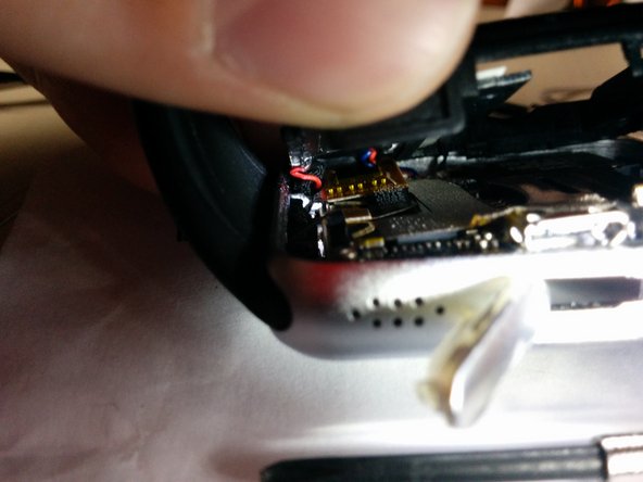
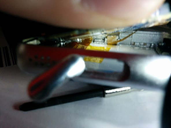
  4. GV30 Teardown: step 4, image 1 of 3 GV30 Teardown: step 4, image 2 of 3 GV30 Teardown: step 4, image 3 of 3
    • Neither the yellow flat cables from the screen.

    Ask FixBot

    Add Comment

  5. GV30 Teardown, Remove the speaker: step 5, image 1 of 3 GV30 Teardown, Remove the speaker: step 5, image 2 of 3 GV30 Teardown, Remove the speaker: step 5, image 3 of 3
    • Levering the speaker with something sharp from its location, it's glued to the base and I damaged it

    Ask FixBot

    Add Comment

  6. GV30 Teardown, Remove the black tape: step 6, image 1 of 3 GV30 Teardown, Remove the black tape: step 6, image 2 of 3 GV30 Teardown, Remove the black tape: step 6, image 3 of 3
    • Remove the black/yellow tape from the plastic frame with something

    Ask FixBot

    Add Comment

  7. GV30 Teardown, Now only the red&black cables are connected: step 7, image 1 of 2 GV30 Teardown, Now only the red&black cables are connected: step 7, image 2 of 2
    • Lift the plastic frame to view the circuit

    • The gray wire cloth used for cooling or shielding blocks the view of the chip below it.l, so remove it

    Ask FixBot

    Add Comment

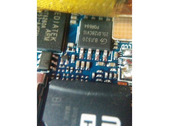
  8. GV30 Teardown, Look at the elements of the circuit: step 8, image 1 of 3 GV30 Teardown, Look at the elements of the circuit: step 8, image 2 of 3 GV30 Teardown, Look at the elements of the circuit: step 8, image 3 of 3
    • Mediatek mt6260a processor

    • ??

    Ask FixBot
    Add Comment

  9. GV30 Teardown, Have a look under the circuit at the flex or flat cables: step 9, image 1 of 1
    • There are 2 cables :

    • 1

    • 2

    Ask FixBot

    Add Comment

  10. GV30 Teardown, Cable 1: step 10, image 1 of 3 GV30 Teardown, Cable 1: step 10, image 2 of 3 GV30 Teardown, Cable 1: step 10, image 3 of 3
    • Seems to be soldered to the board, applying a slight pressure nothing happens. Maybe there's some glue

    Ask FixBot

    Add Comment

  11. GV30 Teardown, Cable 2: step 11, image 1 of 3 GV30 Teardown, Cable 2: step 11, image 2 of 3 GV30 Teardown, Cable 2: step 11, image 3 of 3
    • This cable seems to have the locking bar, but trying to move it sliding or leveraging ir with a screwdriver it doesn't move. How can I remove it ?

    Ask FixBot

    Add Comment

  12. GV30 Teardown, Cable 3: step 12, image 1 of 3 GV30 Teardown, Cable 3: step 12, image 2 of 3 GV30 Teardown, Cable 3: step 12, image 3 of 3
    • Another cable having a locking bar. I tried to move this cable too and having more space I forced it more than the previous one but nothing moved.

    Ask FixBot

    Add Comment

  13. GV30 Teardown, Another cable going into the strap: step 13, image 1 of 3 GV30 Teardown, Another cable going into the strap: step 13, image 2 of 3 GV30 Teardown, Another cable going into the strap: step 13, image 3 of 3
    • I don't know what cable is it , the watch don't measures heartbeats but only steps and monitores sleep. However this cable is soldered and i don't want to desoldering it if not necessary

    Ask FixBot

    Add Comment

  14. GV30 Teardown, The last thing i notice is this chip: step 14, image 1 of 3 GV30 Teardown, The last thing i notice is this chip: step 14, image 2 of 3 GV30 Teardown, The last thing i notice is this chip: step 14, image 3 of 3
    • The chip is connected with the third cable

    Ask FixBot

    Add Comment

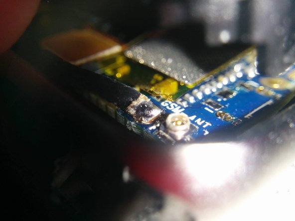
  15. GV30 Teardown, See the bt_ant near the on/off button: step 15, image 1 of 2 GV30 Teardown, See the bt_ant near the on/off button: step 15, image 2 of 2
    • I had to remove the micro sd to see it, also if i described the same antenna in 6th step whitout realizing. It seems to have only 1 connection to the board and seems to be 1 thin copper plate all united. Unfortunately i ripped the antenna in the 2nd photo ! Now i need to replace the antenna with another.

    Ask FixBot

    Add Comment

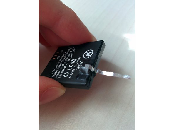
  16. GV30 Teardown, The antenna i have is a simple wifi's one (i think: step 16, image 1 of 3 GV30 Teardown, The antenna i have is a simple wifi's one (i think: step 16, image 2 of 3 GV30 Teardown, The antenna i have is a simple wifi's one (i think: step 16, image 3 of 3
    • The problem is that this antenna have 2 connections while the previous had only 1 ! I don't know what are these connections. Maybe one connects simply to ground, but i don't know. I think it's a SMA connector. I expect if i peel the cable to get 2 cables.

    Ask FixBot

    Add Comment

  17. GV30 Teardown, Completed !: step 17, image 1 of 3 GV30 Teardown, Completed !: step 17, image 2 of 3 GV30 Teardown, Completed !: step 17, image 3 of 3
    • The cable is about 2cm long and wide 2mm , i not measured it but works very well. I don'k know even if it touches the contact or is only near it.

    • If i connect another piece of wire on the antenna the range of the bluetooth remain practically the same. Maybe to increase further the range, i need a determinate-lenght wire , for example with a online calculator the lenght of the ideal antenna results a quarter of wave of 2,450 ghz but i don't know how much is important

    Ask FixBot

    Add Comment

Essenza Bocciolo

Member since: 03/17/16

43 Reputation

1 Guide authored

1 Guide Comment

My strap got deattached by kids any remedy ??

nikita Gupta - Reply Share

Add Comment

View Statistics:

Past 24 Hours: 0

Past 7 Days: 0

Past 30 Days: 10

All Time: 1,878