Introduction
When the speed control potentiometer goes bad, the speed dial may still increase and decrease the speed but the unit will intermittently surge to full speed for a second or two and splash the contents all over your kitchen - incredibly annoying but fixable!
What you need
-
-
-
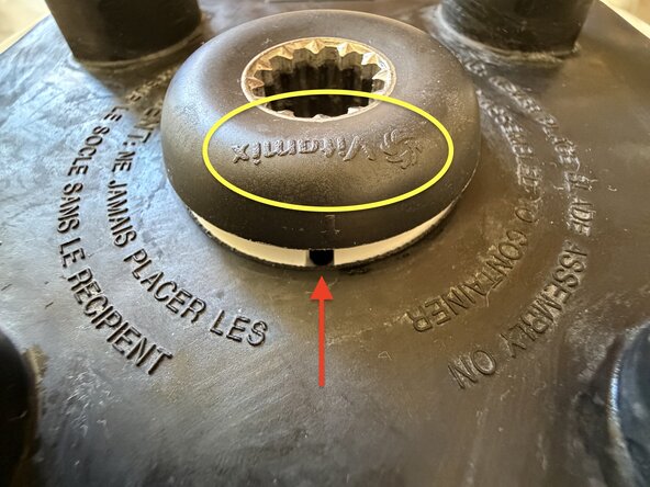
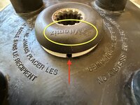
Turn the blender around and find the small hole at the back of the drive socket area. Rotate the drive socket so the logo is aligned with the hole.
-
Insert a 2mm or 5/64" hex key through the hole at an angle about 10° above horizontal (using a ball-tip hex drive helps). Back the cap screw out far enough to lift the drive socket free. Set aside.
-
If the screw falls into the motor, you may be able to retrieve it once you remove the cover in the next steps. If you dropped it on your shag carpet or the dog ate it, the replacement part is a #2-56 x 3/16" stainless steel cap screw.
-
-
-
Lift the rubber top free by pulling it straight up.
-
Using a #2 Phillips screwdriver, remove the four screws underneath.
-
-
-
Slowly pull the top cover of the bender free from the base. It will feel stuck, as there are rubber gaskets between the cover and base to dampen vibration.
-
Once the cover is off, check to see if any of the gaskets got pulled off the base. Reposition them if necessary.
-
NOTE: There will be wires going from the switches and speed control between the cover and the circuit board. Set the cover on its side next to the motor but be careful to not yank on the wires.
-
-
-
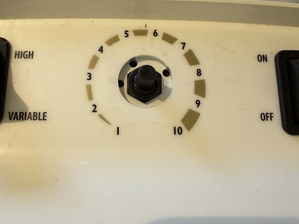
Pull the speed control knob straight out from the housing. It is a slip fit.
-
Use a 13mm deep socket to unscrew the retaining nut from the shaft. Set knob and retaining nut aside.
-
Pull the old potentiometer out of the hole from the inside of the housing.
-
-
-
-
If you have a camera handy, take a picture so you know how the wires are supposed to be connected in the event you decide to unplug some of them.
-
Using needle nose pliers, pull the two faston connectors off of their studs. I marked my wires with a sharpie - one stripe for the upper wire and two stripes for the lower wire, although this step is unnecessary as the speed control will work correctly regardless of wire position.
-
Remove the potentiometer and its wire harness.
-
-
-
Place the old potentiometer in a hobby vise, held by the shaft.
-
Slit the old heat shrink tubing with a razor blade or hobby knife and remove it.
-
Use a soldering iron set to 374° and desolder each wire in turn.
-
Save the wire harness but you can discard the old potentiometer.
-
-
-
The old potentiometer part number is Bourns PCW1J-C24-SL0035L 5KΩ linear. I was unable to locate this exact part but Digikey had a Bourns PCW1J-C24-BAB502L, which had the exact same specs and form factor except for circuit board pins instead of soldering tabs. Cost was $6.77 plus S&H.
-
The new potentiometer has a metal jacket to allow soldering to a printed circuit board. Remove by inserting a pry tool in the crack between the plastic body and the metal jacket and pry enough to pop the jacket off the plastic boss holding it in place. Repeat on the other side, then remove the metal bracket and discard.
-
-
-
Insert shaft of new potentiometer into hobby vise with the pins on the upper side facing you.
-
Using no-clean lead-free solder (Kester 24-6337-8834 with 245 flux or equivalent), tin the two pins on the LEFT side.
-
Use wire cutters to cut off the pin on the RIGHT side.
-
Do not screw up and cut the wrong pin off like I did.
-
Put two 5/8" pieces of 1/8" (3m) heat shrink tubing on each lead of the wire harness and push them out of the way while you solder.
-
Solder one lead to the middle pin and the other lead to the LEFT pin.
-
Push the heat shrink down over each solder joint and shrink with a heat gun or solder rework station.
-
-
-
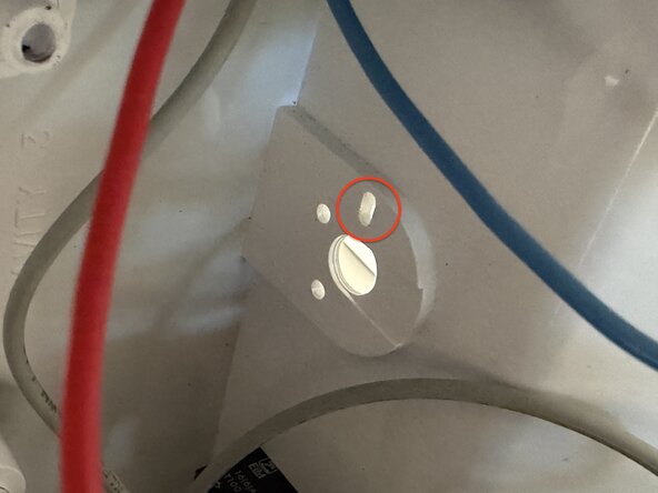
The front of the potentiometer has a projecting tab that aligns with a hole in the cover to keep it from rotating when the knob is turned.
-
Insert potentiometer shaft through the hole, aligning the tab with the smaller hole indicated in the photo.
-
While holding the potentiometer with one hand, thread the retaining nut back onto the shaft with the other hand.
-
Tighten the nut with the 13mm deep socket.
-
Replace the speed control knob onto the potentiometer shaft. It is a friction fit.
-
-
-
Reconnect the faston connectors from the wiring harness to the studs on the circuit board. It doesn't matter which wire goes to which tab.
-
Taking care not to bend the connectors you just soldered on the potentiometer, replace the cover over the motor and push down to seat the cover against the rubber vibration dampeners.
-
Insert the four screws through the top, turn backwards until you feel or hear the threads drop into position then tighten with a #2 Phillips driver.
-
-
-
Clean and rinse the rubber bolster with some soapy water and an old toothbrush. Your significant other will appreciate this.
-
Place the rubber bolster back over the protrusions on the top of the blender case and press firmly to seat.
-
Replace the drive socket, reversing the directions for removal reviewed previously. Use a 5/64 or 2mm ball-tip hex key for ease of reattachment.
-
-
-
Assuming you have no parts left over, plug the blender into a power outlet.
-
Turn the speed knob all the way down.
-
Flip the ON switch. The blender should start up at very low speed but should idle nicely with no sudden speed surges. Slowly increase the speed dial. You should experience a smooth ramp-up of speed, again with no sudden glitches or surges.
-
If everything works OK, you're all done!
-
 Ask FixBot







Give yourself a pat on the back for a job well done!
Cancel: I did not complete this guide.
One other person completed this guide.