
Swagtron T3 Cover Replacement

Klara Perkins and 4 other contributors
Last updated on Jun 19, 2017
Views: 5.8K
View statistics:
- Past 24 Hours:
- 0
- Past 7 Days:
- 6
- Past 30 Days:
- 27
- All Time:
- 5,751
Comments: 0
No one has left comments on this guide. Will you be first?
Go to guide commentsCompleted: 0 1
No one has marked this guide "completed." Will you be the first?
1 person has marked this guide "completed." It's you — great job!
Favorites: 0 1
No one has favorited (and subscribed to) this guide. Will you be the first?
1 person has favorited (and subscribed to) this guide — and that's you!
Introduction
Go to step 1 ↓To replace other components in the Swagtron T3, you will need to first remove the outer shell by removing the screws. Make sure to take note of where each type of screw goes to streamline the process of putting it back together. To avoid electric shock, discharge the capacitors using the capacitor discharge tool before making any changes to your Swagtron. Click here to learn how to safely discharge a capacitor.
What you need

-
-
-
Flip the Swagtron so that the footpads are facing the ground.
-
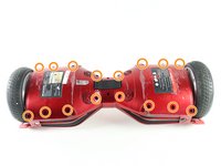
Unscrew the sixteen 9.4 mm Phillips #1 machine screws on the side of the Swagtron that is now facing upwards.
 Ask FixBot
-
-
-
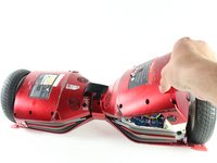
Slowly lift the backside cover.
-
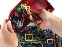
Detach the four cables connected to the cover by pinching the connector clips and pulling the cables out:
-
Three cables on the motherboard side.
-
Two red cables with white connectors and one white cable with a white connector.
-
One yellow cable with a black connector on the battery side.
-
-
-





To reassemble your device, follow these instructions in reverse order.

Team

Cal Poly, Team S13-G3, Forte Spring 2017 Member of Cal Poly, Team S13-G3, Forte Spring 2017
CPSU-FORTE-S17S13G3
4 Members
48 Guides authored
