Free Shipping on Domestic Orders $75+

Soundboks 4 PCBA Replacement

Views: 36

View statistics:

Past 24 Hours:
2
Past 7 Days:
18
Past 30 Days:
36
All Time:
36
Comments: 0

No one has left comments on this guide. Will you be first?

Go to guide comments
Completed: 1

1 person has marked this guide "completed." Will you be next?

Favorites: 1

1 person has favorited (and subscribed to) this guide. Will you be next?

Time Required: 30 minutes
Difficulty: Moderate
Community-Contributed Guide

An awesome member of our community made this guide. It was not created by iFixit staff.

Soundboks 4 PCBA Replacement

Introduction

Go to step 1 ↓

Sometimes your SOUNDBOKS just isn't feeling it. Weird lights, won't turn on, no sound, that sort of thing.

The usual suspect is the PCBA. It's the electronics board, the brain and heart of the whole thing, and sometimes it needs replacing.

Note: Every PCBA is pre-configured with your speaker's serial number and Team-ID.
Order it by contacting customer service on www.soundboks.com

    1. Soundboks 4 PCBA Replacement, Getting Ready: step 1, image 1 of 2 Soundboks 4 PCBA Replacement, Getting Ready: step 1, image 2 of 2
      • Turn off your speaker by disconnecting the battery

      Ask FixBot

      Add Comment

    2. Soundboks 4 PCBA Replacement, Remove the Volume Knob: step 2, image 1 of 3 Soundboks 4 PCBA Replacement, Remove the Volume Knob: step 2, image 2 of 3 Soundboks 4 PCBA Replacement, Remove the Volume Knob: step 2, image 3 of 3
      • Unscrew the Volume Knob by using the 2.5mm Hex/Allen Key

      • Remove the nut and washer using the 10mm Socket Tool

      Ask FixBot

      Add Comment

    3. Soundboks 4 PCBA Replacement, Remove the UI Panel: step 3, image 1 of 3 Soundboks 4 PCBA Replacement, Remove the UI Panel: step 3, image 2 of 3 Soundboks 4 PCBA Replacement, Remove the UI Panel: step 3, image 3 of 3
      • Unscrew the UI panel with the 3mm Hex bit - 6 screws in total

      • Pull the panel out at an angle. Pulling it straight can damage the PCBA!

      Ask FixBot

      Add Comment

    4. Soundboks 4 PCBA Replacement, Disconnect Red & White Wires: step 4, image 1 of 3 Soundboks 4 PCBA Replacement, Disconnect Red & White Wires: step 4, image 2 of 3 Soundboks 4 PCBA Replacement, Disconnect Red & White Wires: step 4, image 3 of 3
      • Unplug all Molex style connectors

      • Only remove Red & White cables now - 6 wires in total

      Ask FixBot

      Add Comment

    5. Soundboks 4 PCBA Replacement, Disconnect Antenna Cable: step 5, image 1 of 3 Soundboks 4 PCBA Replacement, Disconnect Antenna Cable: step 5, image 2 of 3 Soundboks 4 PCBA Replacement, Disconnect Antenna Cable: step 5, image 3 of 3
      • Cut the zip-tie on the antenna cable (from the backside)

      • Pull (don't cut) the glued cable off the PCBA using the cutter tool

      • Disconnect the antenna cable

      • Be careful not to damage the cable

      Ask FixBot

      Add Comment

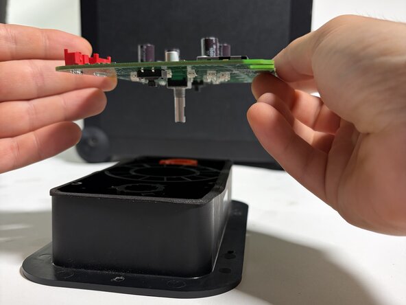
    6. Soundboks 4 PCBA Replacement, Unscrew the Screws: step 6, image 1 of 3 Soundboks 4 PCBA Replacement, Unscrew the Screws: step 6, image 2 of 3 Soundboks 4 PCBA Replacement, Unscrew the Screws: step 6, image 3 of 3
      • Using a 2mm Hex, unscrew all screws - 4 in total.

      • Remove the PCBA from the plastic housing

      Ask FixBot

      Add Comment

    7. Soundboks 4 PCBA Replacement, Mount the New PCBA: step 7, image 1 of 3 Soundboks 4 PCBA Replacement, Mount the New PCBA: step 7, image 2 of 3 Soundboks 4 PCBA Replacement, Mount the New PCBA: step 7, image 3 of 3
      • 4 Screws back in - don't over-tighten!

      • Antenna cable back on - use a zip-tie and cut of the excess

      • Add a small drop of silicone glue (at the red arrow)

      • If using a glue substitute, make sure it is not corrosive or hot-glue

      Ask FixBot

      Add Comment

    8. Soundboks 4 PCBA Replacement, Re-mounting the Volume Knob: step 8, image 1 of 3 Soundboks 4 PCBA Replacement, Re-mounting the Volume Knob: step 8, image 2 of 3 Soundboks 4 PCBA Replacement, Re-mounting the Volume Knob: step 8, image 3 of 3
      • Add the washer first, then the 10mm nut

      • Tighten the 10mm nut

      • The encoder has a flat side - match this side with the volume knob screw

      • Add pressure from top while tightening with the 2.5mm key

      • No power tools here - stuff may break

      Ask FixBot

      Add Comment

Conclusion

To reassemble your device, follow these instructions in reverse order.

Cancel: I did not complete this guide.

One other person completed this guide.

SOUNDBOKS Tech Crew

Member since: 09/17/26

1 Reputation

4 Guides authored

0 Guide Comments

Add Comment

View Statistics:

Past 24 Hours: 2

Past 7 Days: 18

Past 30 Days: 36

All Time: 36