
Separating Main Board

Brian W and one other contributor
Last updated on Mar 17, 2022
Views: 1.3K
View statistics:
- Past 24 Hours:
- 1
- Past 7 Days:
- 13
- Past 30 Days:
- 69
- All Time:
- 1,329
Comments: 3
2 comments on steps, 1 guide comment.
Go to guide commentsCompleted: 1 2
1 person has marked this guide "completed." Will you be next?
2 people have marked this guide "completed." Including you — great job!
Favorites: 2 3
2 people have favorited (and subscribed to) this guide. Will you be next?
3 people have favorited (and subscribed to) this guide — including you!
Community-Contributed Guide
An awesome member of our community made this guide. It was not created by iFixit staff.
Introduction
Go to step 1 ↓This Prerequisite-Only guide shows how to remove the front board from the 8BitDo SN30 Pro+
What you need
Tools


-
-
-
Place the controller face down.
-
Remove the battery cover.
-
Remove rechargeable battery or AA batteries.
 Ask FixBot
-
-
-
Remove L2 and R2 trigger buttons by pushing them away from the grips.
-
-
Tool used on this step:Tweezers$4.99
-
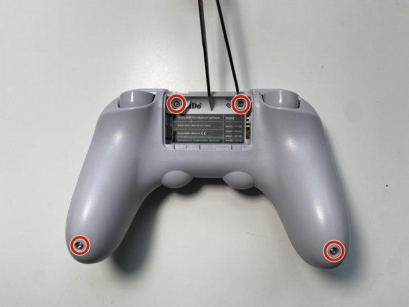
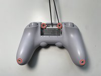
Use Tweezers to uncover two screws under the label in the battery compartment.
-
Use a T6 screwdriver to remove the four 7.3 mm screws securing the rear cover.
-
-
-
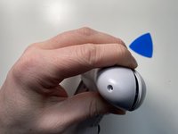
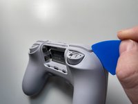
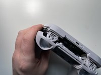
At the end of each grip, pry apart the covers.
-
Use fingernail or opening pick to undo the two top clips.
-
One clip next to L button.
-
One clip next to R button
-
Undo the final clip between the joysticks.
-
-
-
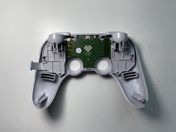
Carefully move the rear cover away and from the front cover. Place it to the left.
-
-
-
-
-
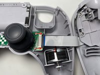
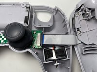
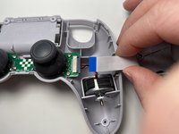
Unlock the ribbon cable by push open the black plastic tab.
-
Pull the ribbon cable out of the connector in the direction of the cable.
-
-
-
-
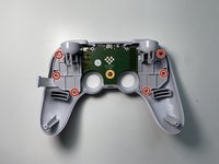
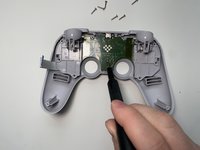
Use a Phillips screwdriver to remove the seven screws securing the main circuit board.
-
Six 10.1mm screws
-
One 5.8mm screws
-
-
-
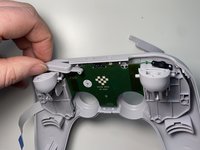
Slide the R buttons up and off its peg.
-
Slide the L button up and off its peg.
-
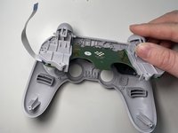
Remove the main board by rotating it towards the USB-C port. Then lift it out.
-
-











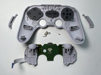
To reassemble your device, follow these instructions in reverse order.
Cancel: I did not complete this guide.
One other person completed this guide.

