This guide has more recent changes. Switch to the latest unverified version.
Introduction
The Samsung Galaxy A16 G5 is disassembled through the back cover. There are some antennas lying underneath the back cover seals, so be careful!
What you need
-
-
-
Prepare the device: Save your content, contacts etc.,
-
turn the device off,
-
and then remove the (SD and SIM) card holder by sticking in the SIM screw driver.
 Ask FixBot
-
-
-
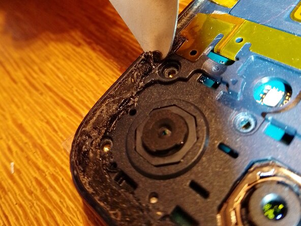
Be careful now: The seals are quite sticky and you may damage the antenna with the metal spudger! The problematic zones are marked in red.
-
Remove the back cover. I removed it with a metal spudger. You may be able to soften the seals with a heat plate, but I decided not to since it is a plastic back cover.
-
-
-
Remove 8 top screws with a Phillips head screw driver J000
-
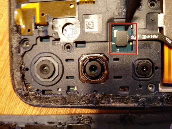
Remove cable with a plastic spudger
-
-
-
Remove 7 bottom screws with a Phillips head screw driver J000
-
-
-
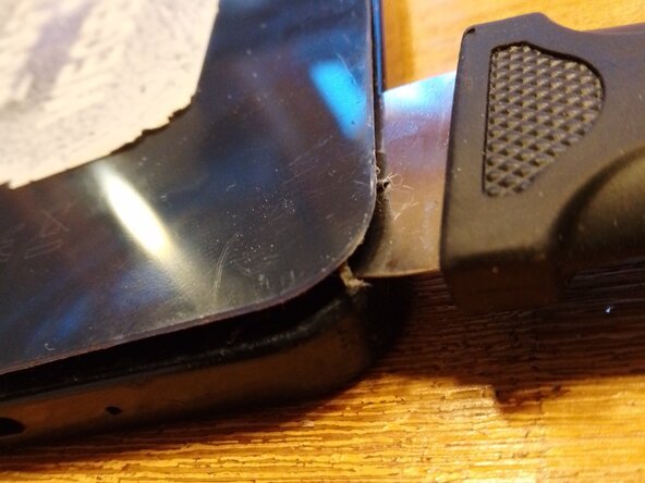
Remove frame from display with a spudger. A metal spudger is used in image. Be careful at the volume buttons, on/off switch and the USB-C cable input.
-
There is no plug that combines both parts, so just lay them next to each other.
-
-
-
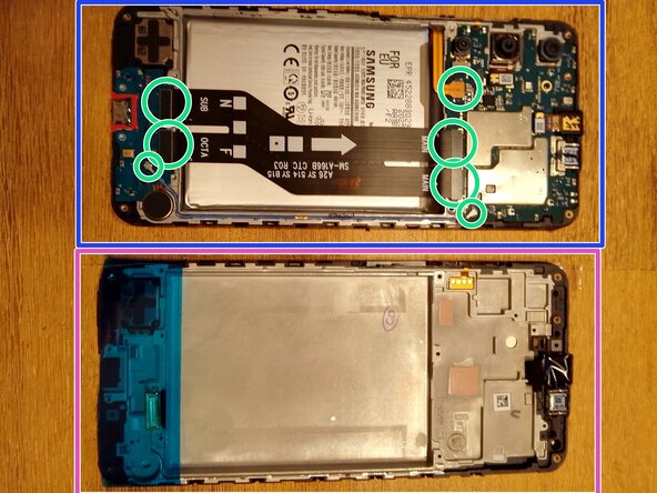
Lay the old display component (blue) next to the new one (pink).
-
Remove 7 plugs of cables in the old display component with a plastic spudger.
-
-
-
-
Unscrew 1 black screw on the top mainboard with a phillips head J000 screw driver.
-
Lift top mainboard with a plastic spudger and remove it from the display component
-
-
-
Unscrew 1 black screw on the bottom I/O-board with a phillips head J000 screw driver.
-
Lift the bottom I/O-board and remove it from the display component.
-
-
-
The battery is glued in, so you need to apply a lever. I used a flat head screw driver.
-
Lift the battery and remove it from the display component
-
Lift the round component next to the battery (vibration motor) with a plastic spudger or tweezers.
-
-
-
You have now disassembled the following parts:
-
Card slide (red)
-
Back cover + Frame (blue)
-
2 cables (green)
-
Bottom I/O board+ 7 silver screws + 1 black screw (orange); Top main board +8 silver screws + 1 black screw (yellow)
-
2 Glued components: battery and vibration motor (pink)
-
Old display component (no color)
-
-
-
On the new display component:
-
Remove the small black plastic cover for the front camera
-
Remove the plastic strip on the bottom. Leave the front cover on the display for now to save it from damage
-
Flip the new display component to reveal the inside
-
Now do everything in reverse order as in the disassembly step on the new display component
-
-
-
Into the new display component:
-
Insert the battery. It is still sticky so you normally do not need any glue
-
Insert the round vibration motor into the new display component.
-
-
-
Insert the (larger) top mainboard into the new display component and screw in one of the two black screws
-
Insert the (smaller) bottom I/O-board into the new display component and screw in one of the two black screws
-
-
-
Press the 8 plugs of the cables softly with your fingertips. They shold give in softly.
-
Hide the blue cable in the frame with the tip of a spudger
-
-
-
Clean the frame with a metal spudger or methanol on a cotton swab
-
Press the frame firmly onto the display component until it clicks on each side.
-
Fasten the dangling cable
-
-
-
Screw in all silver screws:
-
7 on the bottom of the frame
-
8 on the top of the frame
-
For the seals:
-
Find the side of the seal that needs to stick to the back cover.
-
Take the plastic foil of that side of the seal and glue it on the back cover
-
Take the plastic foil of the other side of of the seal off and glue the back cover with the seal on the display/frame component
-
Insert SIM-card and SD-card slide and turn on.
-
-









Cancel: I did not complete this guide.
3 other people completed this guide.

