
Ryobi P517 Trigger Replacement

Abner Fernandez and 3 other contributors
Last updated on May 15, 2024
Views: 524
View statistics:
- Past 24 Hours:
- 2
- Past 7 Days:
- 17
- Past 30 Days:
- 79
- All Time:
- 524
Comments: 0
No one has left comments on this guide. Will you be first?
Go to guide commentsCompleted: 0 1
No one has marked this guide "completed." Will you be the first?
1 person has marked this guide "completed." It's you — great job!
Favorites: 0 1
No one has favorited (and subscribed to) this guide. Will you be the first?
1 person has favorited (and subscribed to) this guide — and that's you!
Introduction
Go to step 1 ↓Use this guide to remove and replace the trigger on your Ryobi P517 reciprocating saw.
The trigger is responsible for initiating the cutting action of the saw. When you press the trigger, it activates the motor of the saw, causing the blade to start reciprocating. The trigger ensures that the saw only operates when intentionally activated by the user, ensuring additional safety. The trigger assembly needs to be replaced when it is unresponsive or if its connection to the other components is compromised. A poorly installed trigger assembly can impact the movement/response of the blade and the user safety. The trigger is connected to the circuit board assembly, so the circuit board must be replaced to replace the trigger.
Before reading this guide, please review the Ryobi P517 Troubleshooting Guide to ensure that your issue cannot be resolved externally, without removing the trigger. Remove the housing assembly before beginning the trigger removal process.
What you need


-
-
-
Lay the saw flat so the left side is facing up.
-
Remove the grey orbital button by twisting it counterclockwise.
 Ask FixBot
-
-
-
Flip the saw so its right side is facing up.
-
Remove the 10 mm screw using a Torx T27H screwdriver.
-
-
-
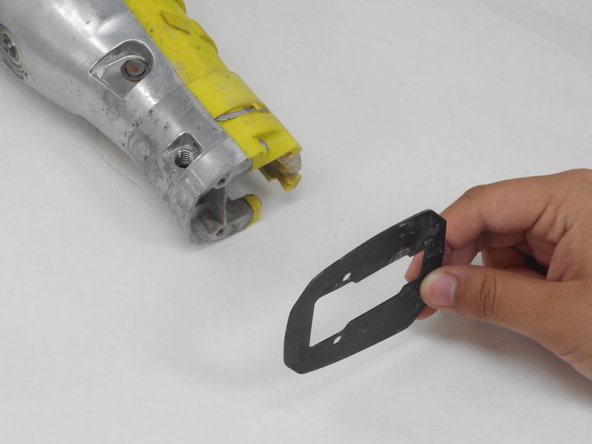
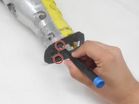
Remove the two 12.5 mm screws from the front of the guide plate using the Torx T10H screwdriver.
-
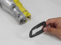
Then remove the guide plate.
-
-
-
Flip the saw so its right side is facing up.
-
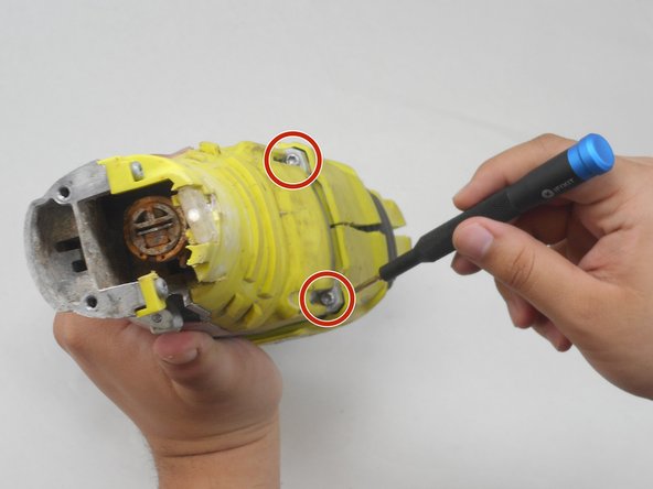
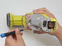
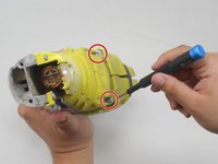
Use the Torx T15H screwdriver to remove the eleven 18.1 mm screws from the housing assembly.
-
-
-
Use a Torx T15H screwdriver to remove the four 30.7 mm screws that are holding the housing assembly with the gear case assembly and gear case cover.
-
-
-
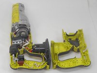
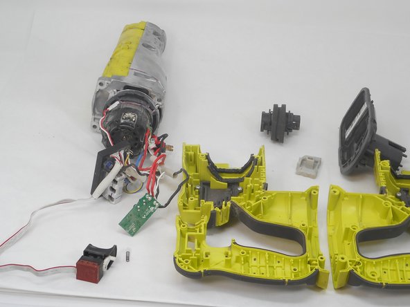
Remove the switch, circuit board, and contact plate holder assembly from the housing assembly.
-
-
-
-
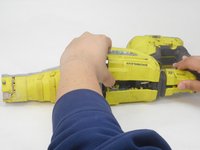
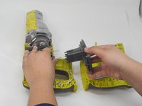
Lift and remove the gear case from the housing assembly and ensure that there are no parts remaining in housing assembly.
-
-
-
-
-
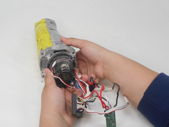
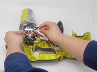
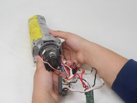
Position the saw so the ports connecting the circuit board assembly to the motor are accessible.
-
-
-
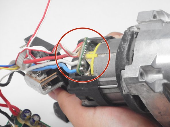
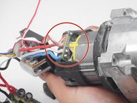
Use the soldering iron and desoldering pump to desolder the circuit board assembly from the motor.
-
-
-
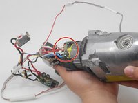
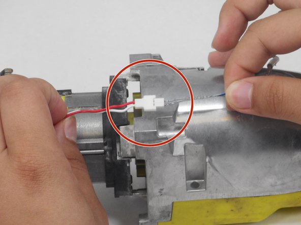
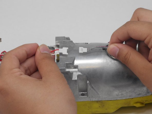
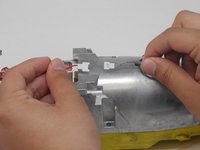
Gently pull the thin red and white wire on opposite ends of its connector to disconnect the LED from the circuit board.
-
-










To reassemble your device, follow these instructions in reverse order.

Team

University of Memphis, Team 4-4, Sneed Spring 2024 Member of University of Memphis, Team 4-4, Sneed Spring 2024
UM-SNEED-S24S4G4
4 Members
48 Guides authored
