This translation was generated by a machine and has not been reviewed by a person yet. Speak this language? Review it.
Introduction
To repair the grinder, first open the device. Unscrew the grinder and lift it out. Then you can also open the grinder, clean it, or replace components (motor, sensor, grinding discs).
What you need
-
-
-
Remove all attachments such as the water tank, brewing unit, bean compartment lid, and drip tray. Remove all coffee beans.
-
Turn the machine over so that the back is facing you. Remove the two Torx T10 screws at the bottom. Pull the back out slightly at the bottom and lift it down.
-
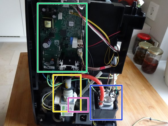
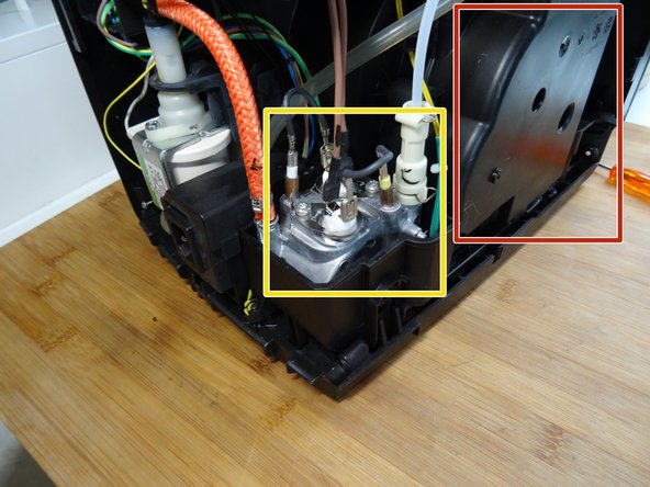
Important components are immediately visible:
-
The main circuit board
-
The pump
-
The flow meter
-
The boiler
 Ask FixBot
-
-
-
Unscrew the Torx T10 screw on the finger guard in the coffee bean compartment.
-
Lift out the finger guard.
-
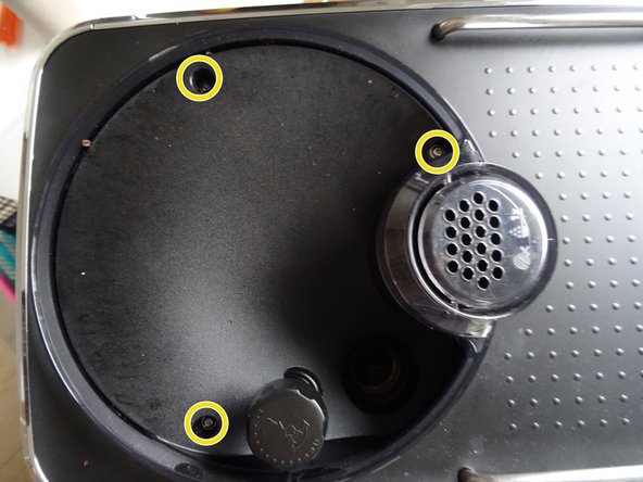
Unscrew the three Torx T10 screws in the coffee bean compartment.
-
-
-
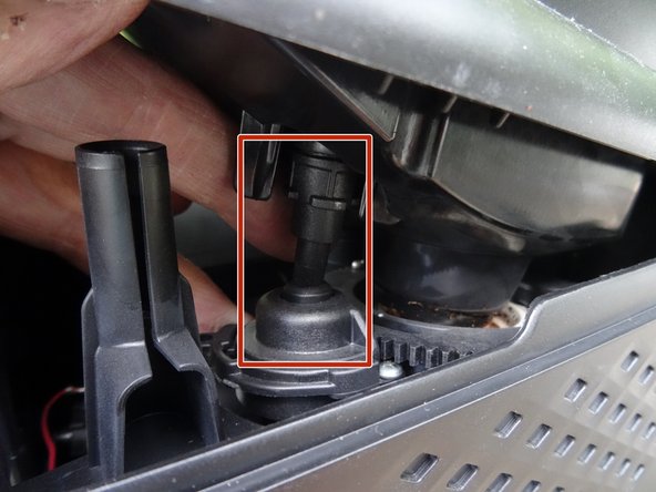
Lift the upper cover slightly at the rear edge.
-
Then lift the cover completely off.
-
When reassembling, make sure that the grinder adjustment is correctly positioned.
-
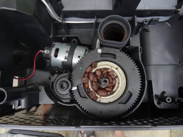
Figure 3 shows the grinding mechanism, which can now easily be removed.
-
-
-
-
Unscrew the two Torx T10 screws at the bottom of the front.
-
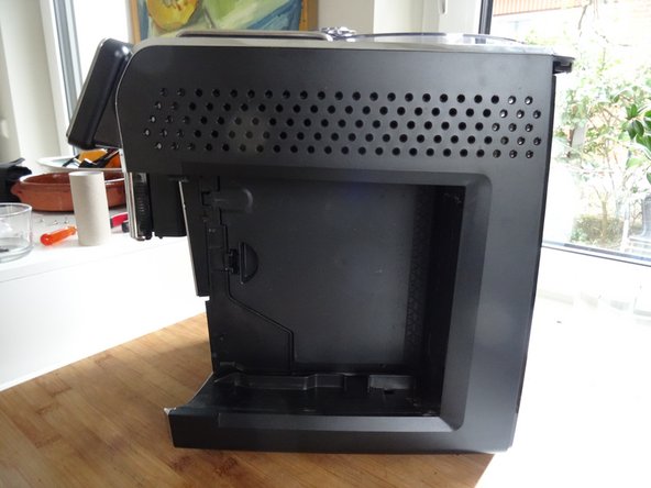
Slide the right side panel back slightly and remove it.
-
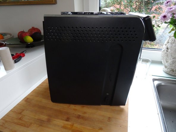
Slide the left side panel back slightly and remove it.
-
-
-
Other important components:
-
The boiler
-
Valve block, consisting of four solenoid valves
-
Grinder
-
Drive
-
-
-
-
-
Take a photo of the mark on the large gear wheel; it should be in the same position when you reassemble it.
-
Although the motor is powered by 230 V, diodes ensure that only positive half-waves are supplied, so that the motor only rotates in one direction. Make a note of how the connection cables are plugged in. Test later to see if it is rotating in the correct direction.
-
You can test the motor with approximately 25 V DC. It should turn easily and draw approximately 120 mA. If this is not the case, check the carbon brushes on the side. Only then should you consider replacing it.
-
Insert translation here
-
Any brackets—in this case, the black rubber sleeve—must be transferred to the new part.
-
The speed sensor can only be removed from the inside. To do this, you must disconnect its plug from the main circuit board and expose the cables.
-
-
-
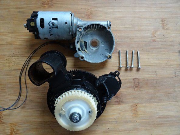
There are four Torx T10 screws on the underside of the grinding mechanism. Remove those.
-
The screw marked in yellow must not be removed when replacing the motor.
-
The white plastic sleeve around the screw marked in yellow must be transferred to the replacement part.
-
Lift off the motor.
-
-
-
The machine's electronic use the sensor to measure the number of revolutions. The sensor must be transferred to the new motor.
-
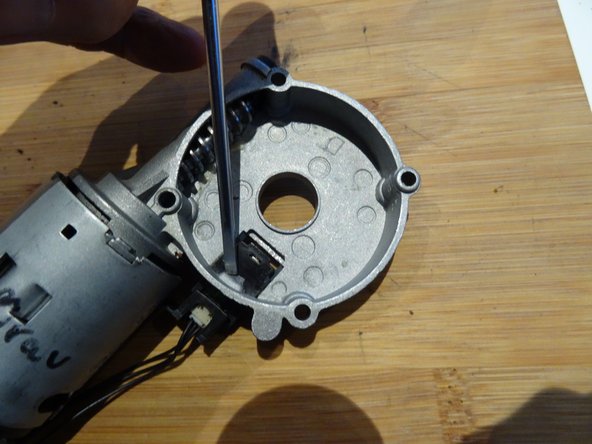
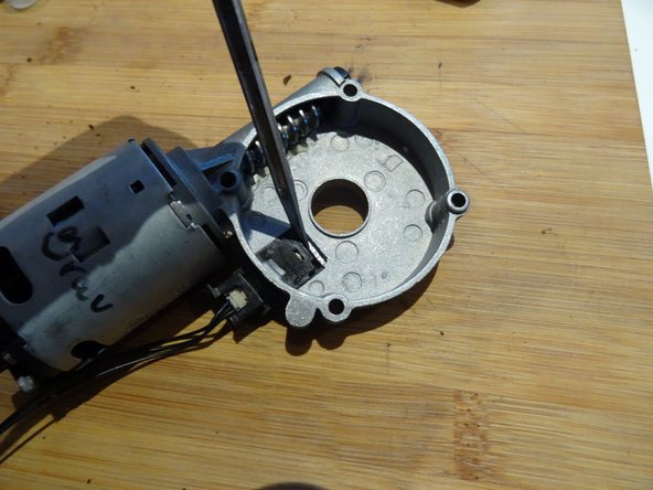
The sensor is secured on the inside with a locking tab. It can therefore only be removed from the inside.
-
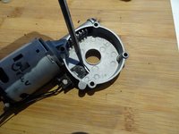
Press the locking tab firmly down with a flat screwdriver.
-
Slide the sensor out, using the flat screwdriver to help if needed.
-
Transfer the sensor to the new part.
-
-
-
Grease the worm gear on the new motor a little; the old grease may be sufficient, but new grease is better.
-
Check that the plastic bushing is seated properly in the center opening. Screw the motor tight.
-
-














Perform the steps in reverse order to reassemble your device.

1 Guide Comment
If error 02 is reported, check the four 100Ohm "101" SMD-resistors. Seems to happen often that one goes open-circuit.
