
REL T3 Main Amplifier Power Resistors Replacement

Jasper van Zuijlen and one other contributor
Last updated on Sep 3, 2026
Views: 121
View statistics:
- Past 24 Hours:
- 2
- Past 7 Days:
- 10
- Past 30 Days:
- 63
- All Time:
- 121
Comments: 0
No one has left comments on this guide. Will you be first?
Go to guide commentsCompleted: 1 2
1 person has marked this guide "completed." Will you be next?
2 people have marked this guide "completed." Including you — great job!
Favorites: 0 1
No one has favorited (and subscribed to) this guide. Will you be the first?
1 person has favorited (and subscribed to) this guide — and that's you!
Community-Contributed Guide
An awesome member of our community made this guide. It was not created by iFixit staff.
What you need
Tools


-
-
-
Place the subwoofer on it legs to protect the driver. Be careful not to touch the driver/speaker on the bottom when you handle the case.
-
Using the 3mm hex tool, remove only the outer rim of screws, starting from the bottom.
-
Make sure to support the plate amp by gripping the heat sink.
-
Remove the top screws. Be aware: the heavy transformer is located at the top. Removing the top screws will probably make the plate amp tilt out of the case.
-
Using the heatsink, carefully lift the plate amp out of the case. Again: it's heavier than you might expect!
 Ask FixBot
-
-
-
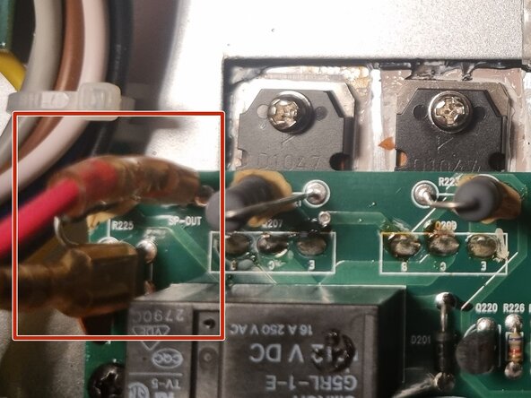
The plate amp is still connected to the driver via faston connectors. I found it easiest to disconnect the driver connectors, but removing them from the amplifier side works equally well.
-
-
-
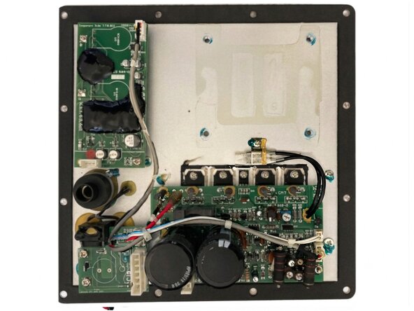
You've now removed the plate amp. Set it aside on the heatsink side. The height of the heatsink will make sure that the controls are not damaged.
-
Now is a good time to check the voltage rails for residual voltage. Everything after the rectifier bridge should be <45V, but always take appropriate precautions when it comes to mains powered devices.
-
-
-
-
-
Snip all tywraps, such that all cables can be manipulated freely.
-
-
-
Disconnect all connectors that tie to the transformer
-
Make sure that all leads can be manipulated freely.
-
-
-
Start loosening the screws on the back using the m3 hex tool
-
Don't remove them fully, yet though.
-
-
-
Turn the amp on it's back.
-
Remove the nuts from the screws that where loosened on the back.
-
Remove the philips screws using a #2.
-
-
-
Loosen the dampening rubber by running a Halberd Spudger underneath it.
-
The rubber is not adhered to the aluminium and is pretty tough, so a moderate amount of force is allowed.
-
-
-
You can now remove the transformer from the plate. Be careful not to damage the controls on the plate now that the assembly is a lot lighter.
-
-
-
-
-
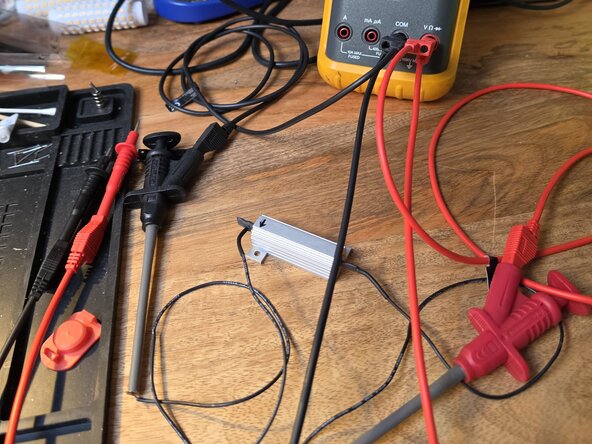
Discharge the capacitor e.g. using a replacement 1k3 power resistor.
-
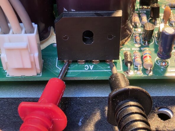
Carefully bridge the resistor across the + and - legs of the recifier, but don't touch anything else.
-
-
-
Verify that the voltage is near zero. 0.2V or so is fine.
-
The voltage starts at around 100V, so be careful.
-
-
-
Remove the screws to the thermistor.
-
Remove the screws to the transistors.
-
Store them in a separate baggy.
-
-
-
Remove screws for four corners.
-
Store them in or on their posts.
-
-
-
Gently lift up the PCB. The transistors might be held down by thermal paste, so use a spudger to release them.
-
-
-
-
Carefully remove silica pads, take note: they are very fragile!
-
Remove excessive black putty where needed.
-
Thoroughly clean back plate with Isopropyl Alcohol (IPA).
-
Clean silica pads as well and store them.
-
-
-
-
-
Cover the electronics with paper and tape.
-
This reduces the risk of drilling chips ending up in the electronics.
-
(Please excuse the dirty plate. If only my repair went as linear as this guide)
-
-
-
At this point you have some options:
-
Tapping
-
Bolting
-
Adhering
-
I don't trust adhesives, and I do not have a tap, so bolting was the only option. I salvaged the M2 screws and nuts from the housing of an old laptop.
-
-
-
Mark the positions in between the heatsink fins.
-
This allows for nuts to be inserted later.
-
Place the transformer back on the plate, and align the resistors in the available space.
-
-
-
-
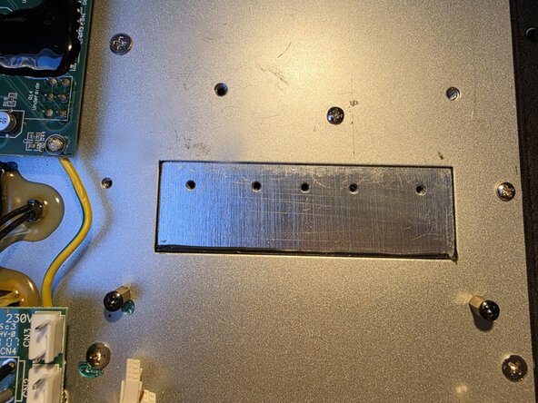
Drill the holes. Aluminum is very grippy, so make sure to use an appropriate cutting oil. I drilled at 2.5mm.
-
Drill the counter holes on the heatsink side to seat the nuts. Make sure not to get any chips or oil in the process! I drilled these holes at 3.5.
-
Deburr the holes so the resistors lie flat on the plate. This improves thermal coupling.
-
-
-
Test fit the resistors and the nuts to make sure everything fits as intended before committing to permanent mounting.
-
I had to tweak the rubber damper under the transformer a bit.
-
-
-
Attach wires to the resistors.
-
Ensure adequate length for installation (you can snip off the excess; adding is harder).
-
-
-
Clean the nut and the heatsink hole thoroughly with IPA.
-
Using epoxy and a toothpick, apply a little on the inside of the screwhole.
-
Fix one nut at a time to preserve alignment.
-
Once dry, remove all screws.
-
-
-
Solder the resistors into place, shorten the wires to fit.
-
Apply thermal paste and mount to the backplate.
-
Apply loctite to the threads.
-
-
-
Hook the amp up to a Dim Bulb Tester. I used a halogen bulb, it works the same.
-
Make sure the light flashes when you turn the amp on, but then dims down.
-
Optionally use this cover on the mains pins, to reduce the risk of electrical shock.
-
-
-
Test the voltage on pin 4 and pin 7
-
Use ground from the speaker connector
-
Voltages should be around:
-
pin4: -14.5V
-
pin 7: 14.5V
-
-
-
Final test before disconnecting the dim-bulb: check that the DC offset on the speaker terminals is zero (or else yuor buying a new driver
-
You're now ready to hook the amp up directly to mains and listen to your music. Enjoy your upgrade!
-
Don't forget to reassemble first ;-)
-
-
-
Optional, but highly recommended for longevity
-
Apply electronics glue to all protruding elements (wires, capacitors, ...)
-
I took a gamble and used Bison PolyMax, since I have no further use for electronics glue. It should be applicable, although impossible to remove. I'll worry about that later.
-
Make sure all tie wraps are in place, so everything is nice and tight.
-
Add some thread locker to the resistors screws.
-
-










To reassemble your device, follow these instructions in reverse order.
Cancel: I did not complete this guide.
One other person completed this guide.

