Introduction
This guide details the disassembly of the film advance mechanism, which is required to replace parts such as the sprocket shaft or the take-up spool.
The removal of just the frame counter assembly can be performed on its own. But any further disassembly requires first disassembling the charging mechanism on the bottom of the camera. The winding spring must be unwound to remove the main wind shaft.
What you need
-
-
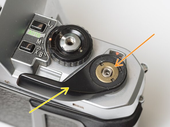
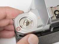
Remove one screw.
-
Lift the release lever and bias spring from the post. Be careful as the spring positioning it is still under tension.
-
Installation Notes: Pay attention to the location of the bias spring during reassembly.
-
-
-
Work the plastic housing off of the left contact pin. The right contact pin will come off with the housing.
-
If desired, the contact and wire can be fully removed from the camera. Soften the contact adhesive with isopropyl alcohol then gently peel away.
-
-
-
Remove one shoulder screw.
-
Remove two screws.
-
Tilt the left side of the linkage up, then lift it away from the chassis.
-
Installation Notes: Make sure that the tab on the advance lock lever sits forward (in camera) of this lever. When the mirror is charged, the lever should move rearward (in camera) allowing the advance lock to engage.
-
-
-
Remove one screw.
-
Lift out wind completion switch. Be careful not to deform the contact legs
-
-
-
Remove one circlip.
-
Lift the lever off the post.
-
Remove the bias spring.
-
-
-
Unhook coil spring from ratchet pawl.
-
Remove one circlip.
-
Lift off ratchet pawl and shim washer.
-
Remove brass bushing.
-
Lift off advance lever lock.
-
Remove bias spring.
-
-
-
-
Remove one screw.
-
Lift out switch assembly.
-
Remove isolator sheet.
-
-
-
Keep a finger on top of the winding spring to hold it in place.
-
Unhook the end of the winding spring from the retaining post.
-
Remove one shim washer.
-
-
-
Remove one screw.
-
Remove one screw.
-
Remove one slotted retaining post.
-
Remove charging mechanism plate.
-
Remove one plastic washer.
-
-
-
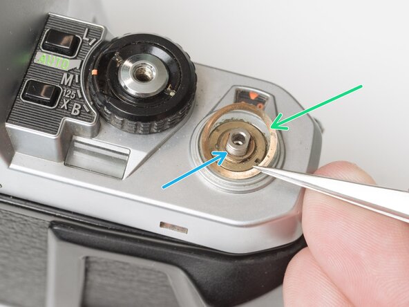
Remove the rubber decorative cap. It is attached with contact cement underneath. Isopropyl Alcohol may be used to soften the adhesive.
-
Unscrew the lock nut using a spanner wrench. The lock nut is reverse threaded.
-
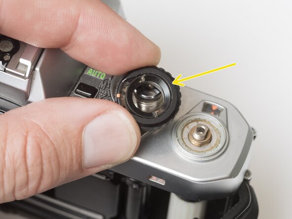
Lift off the advance lever.
-
Remove the spring washer.
-
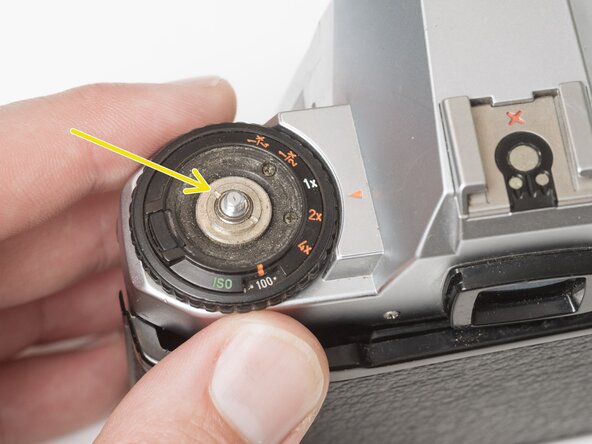
Remove one shim washer.
-
-
-
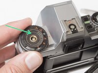
Set the mode dial to the 'L' position.
-
Use a spanner wrench to unscrew the dial lock nut.
-
Lift off the mode dial.
-
-
-
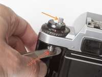
Place a rigid object in the fork.
-
Unscrew the rewind lever.
-
Use a spanner wrench to remove the lock nut.
-
Lift off the exposure compensation dial.
-
-
-
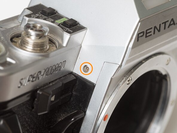
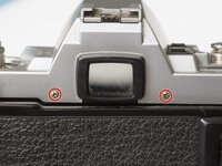
Remove two screws on either side of the eye piece.
-
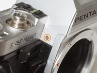
Remove two screws on either side of the lens mount.
-
-
-
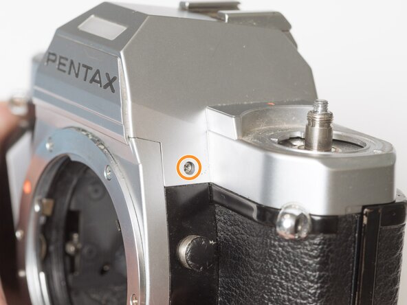
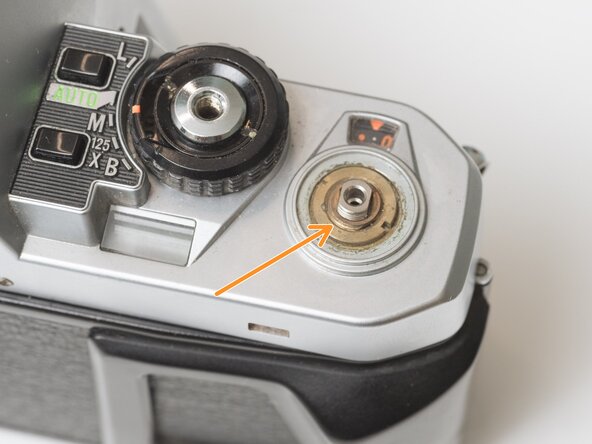
Remove one screw by the exposure compensation dial.
-
Use a spanner wrench to remove the lock nut under the advance lever.
-
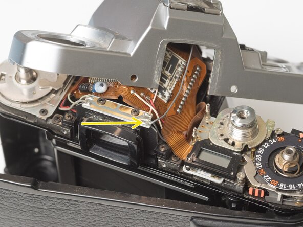
Lift off the top cover slowly. It is still attached by one wire.
-
Unsolder one gray flash sync wire.
-
-
-
Remove one slotted screw.
-
Remove one screw and the frame number indicator.
-
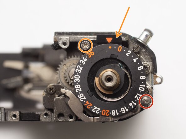
Installation Notes: Position the advance cam as indicated before installing the counter assembly. After installation, make sure to hook the spring near the right side strap lug.
-
-
-
Remove one screw and retainer plate.
-
Pull out main wind shaft. The main wind gear may come with it.
-
-
-
Remove main wind gear.
-
Installation Notes: Ensure that the alignment dot on the main wind gear is matched with the dot on the intermediate gear.
-
-
-
Remove two screws.
-
Remove one countersunk screw.
-
Lift off advance mechanism plate.
-
-
-
Position the sprocket pawl so you can see this slot from the top side.
-
During installation, the sprocket pawl must couple with the tip of the wire coming from the sprocket gear.
-
And the tab on the slipper clutch should sit in the slot in the take-up spool.
-
Proper coupling of sprocket pawl and sprocket gear wire.
-
-
-
Remove one screw.
-
Remove intermediate gear.
-
Remove washer.
-
Installation Notes: During reassembly, make sure that the alignment dot on the intermediate gear matches the slot on alignment slot on the sprocket gear.
-
-
-
Remove one screw. It is often secured with threadlocker.
-
Push the sprocket rod up and slide the pin out.
-
Remove sprocket gear.
-
-
-
Remove wind action washer. This spins when film is properly loaded in the camera, and moves the striped flag to alert the user.
-
Lift out take-up spool.
-
-
-
Pull the inner sprocket rod out from the bottom of the camera.
-
Lift out sprocket shaft.
-


To reassemble your device, follow these instructions in reverse order.