
Pentax MX Mirror Box Removal

Sam Gustafson and one other contributor
Last updated on Jul 9, 2026
Views: 436
View statistics:
- Past 24 Hours:
- 6
- Past 7 Days:
- 24
- Past 30 Days:
- 115
- All Time:
- 436
Comments: 0
No one has left comments on this guide. Will you be first?
Go to guide commentsCompleted: 0 1
No one has marked this guide "completed." Will you be the first?
1 person has marked this guide "completed." It's you — great job!
Favorites: 0 1
No one has favorited (and subscribed to) this guide. Will you be the first?
1 person has favorited (and subscribed to) this guide — and that's you!
Community-Contributed Guide
An awesome member of our community made this guide. It was not created by iFixit staff.
Introduction
Go to step 1 ↓Removing the mirror box is often necessary to troubleshoot issues and access mechanisms for cleaning. The mechanisms on the side and bottom of the mirror box are common sources of a jammed camera.
What you need
Tools


-
-
-
Remove the lever cap. The cap is reverse threaded.
-
Lift off the advance lever.
-
Remove the collar beneath the lever.
 Ask FixBot
-
-
-
Set the ISO to 100 and the shutter speed to 1000.
-
Remove one pin head screw.
-
Lift off shutter speed dial.
-
Remove the collar beneath the dial.
-
Installation Notes: Make sure that the tab on the shutter speed resistor mates properly with this slot on the shutter speed dial.
-
-
-
Place a tool in the fork of the rewind shaft. Turn the rewind knob counterclockwise to loosen it.
-
Remove the lock ring underneath the rewind knob.
-
Remove the cover plate.
-
-
-
Remove two M1.7 x 3.2 mm screws.
-
Remove two M1.7 x 2 mm countersunk screws.
-
Lift off top cover.
-
The release cable pin in the shutter button is loose and may fall out.
-
-
-
-
-
Apply isopropyl alcohol to soften the leatherette adhesive.
-
Turn the self-timer lever to the charged position.
-
Peel the leatherette off the camera body, carefully working it over the self-timer lever.
-
Remove one loose cover panel.
-
Repeat for the opposite panel.
-
-
-
Unsolder two yellow wires for the aperture resistor.
-
-
-
Remove four M1.9 x 3.9 mm screws.
-
Lift off front board.
-
Look for shim washers at the screw locations and note their positions.
-
-
-
-
-
Remove three M1.7 x 2.0 mm countersunk screws.
-
Lift off bottom cover.
-
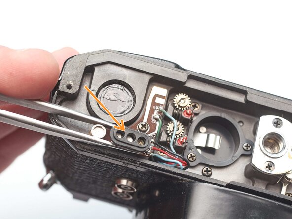
Remove loose plastic housing for motor drive contacts.
-
-
-
-
-
Remove four M1.9 x 3.8 mm screws.
-
Lift off light baffle.
-
Use isopropyl alcohol to soften adhesive and detach wires from the backside of the baffle.
-
-
-
Unsolder two brown wires for the shutter speed resistor.
-
-
-
Unsolder one gray for the x-sync.
-
Unsolder one white wire for the FP sync.
-
-
-
Unsolder one green wire for the motor drive connection.
-
Unsolder one blue wire for the LED switch.
-
Unsolder one red wire and one black wire.
-
-
-
-
Open up wire routing guides and remove all wires from them.
-
Pull the black and red wires out of the hole in the bottom of the chassis.
-
Make sure the gray wire is free and can pull away with the mirror box.
-
-
-
Remove one M1.4 x 2.8 mm screw and washer.
-
Remove one M1.7 x 2.8 mm screw.
-
Pull the LED PCB out of the side of the mirror box.
-
-
-
Loosen the slotted post but do not remove.
-
Slide the idler gear back so that it no longer engages with the speed indicator disc.
-
-
-
Remove two M1.7 x 4.6 mm screws.
-
Remove two slotted posts.
-
Lift the mirror box up and tilt the top forward to remove it.
-
-
-
Temporarily install the wind lever and the shutter speed dial.
-
Wind the camera.
-
Press the shutter release button.
-
Release the opening curtain latch. This is usually done by the mirror box but has to be done manually in this case.
-
-




To reassemble your device, follow these instructions in reverse order.

