
Free Shipping on Domestic Orders $75+

Pentax MX Main PCB Removal

What you need

  1. Pentax MX Main PCB Removal, Remove film advance lever: step 1, image 1 of 3 Pentax MX Main PCB Removal, Remove film advance lever: step 1, image 2 of 3 Pentax MX Main PCB Removal, Remove film advance lever: step 1, image 3 of 3
    • Remove the lever cap. The cap is reverse threaded.

    • Lift off the advance lever.

    • Remove the collar beneath the lever.

    Ask FixBot

    Add Comment

  2. Pentax MX Main PCB Removal, Remove shutter speed dial: step 2, image 1 of 2 Pentax MX Main PCB Removal, Remove shutter speed dial: step 2, image 2 of 2
    • Set the ISO to 100 and the shutter speed to 1000.

    • Remove one pin head screw.

    • Lift off shutter speed dial.

    • Remove the collar beneath the dial.

    • Installation Notes: Make sure that the tab on the shutter speed resistor mates properly with this slot on the shutter speed dial.

    Ask FixBot

    Add Comment

  3. Pentax MX Main PCB Removal, Remove rewind knob: step 3, image 1 of 3 Pentax MX Main PCB Removal, Remove rewind knob: step 3, image 2 of 3 Pentax MX Main PCB Removal, Remove rewind knob: step 3, image 3 of 3
    • Place a tool in the fork of the rewind shaft. Turn the rewind knob counterclockwise to loosen it.

    • Remove the lock ring underneath the rewind knob.

    • Remove the cover plate.

    Ask FixBot

    Add Comment

  4. Pentax MX Main PCB Removal, Remove top cover: step 4, image 1 of 3 Pentax MX Main PCB Removal, Remove top cover: step 4, image 2 of 3 Pentax MX Main PCB Removal, Remove top cover: step 4, image 3 of 3
    • Remove two M1.7 x 3.2 mm screws.

    • Remove two M1.7 x 2 mm countersunk screws.

    • Lift off top cover.

    • The release cable pin in the shutter button is loose and may fall out.

    Ask FixBot

    Add Comment

  5. Pentax MX Main PCB Removal, Unsolder connections: step 5, image 1 of 3 Pentax MX Main PCB Removal, Unsolder connections: step 5, image 2 of 3 Pentax MX Main PCB Removal, Unsolder connections: step 5, image 3 of 3
    • Unsolder one blue wire for the LED switch.

    • Unsolder one green wire for the motor drive.

    • Unsolder two yellow wires for the aperture resistor.

    • Unsolder two brown wires for the shutter speed resistor.

    • Unsolder one gray wire for flash sync.

    Ask FixBot

    Add Comment

  6. Pentax MX Main PCB Removal, Disconnect LED PCB: step 6, image 1 of 2 Pentax MX Main PCB Removal, Disconnect LED PCB: step 6, image 2 of 2
    • Remove one M1.4 x 2.8 mm screw and washer.

    • Remove one M1.7 x 2.8 mm screw.

    • Pull the LED PCB out of the side of the mirror box.

    • Installation Notes: Install batteries and check the position of the LEDs. Position the PCB as needed then tighten the screws to fix it in place.

    Ask FixBot

    Add Comment

  7. Pentax MX Main PCB Removal, Detach light cell PCB: step 7, image 1 of 2 Pentax MX Main PCB Removal, Detach light cell PCB: step 7, image 2 of 2
    • Remove two screws.

    • Lift of flash sync connector.
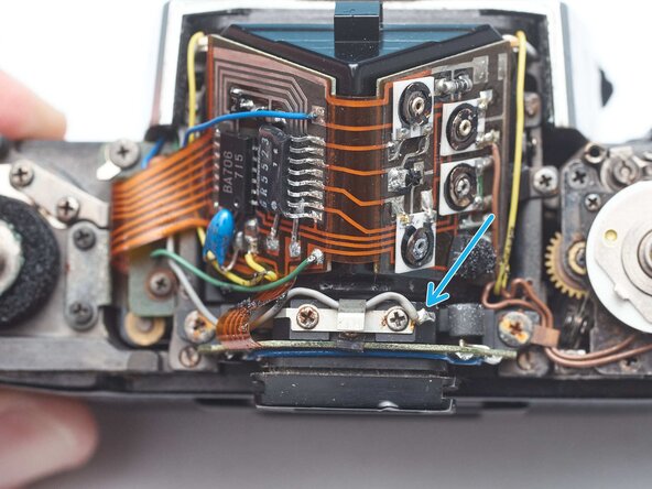
    • Remove one screw.

    • Remove light cell PCB clamp

    • Slide the light cell PCB up and off the eye piece.

    Ask FixBot

    Add Comment

  8. Pentax MX Main PCB Removal, Loosen adhesive: step 8, image 1 of 2 Pentax MX Main PCB Removal, Loosen adhesive: step 8, image 2 of 2
    • Use isopropyl alcohol to loosen the adhesive attaching the PCB to the prism.

    • Use a soft, thin tool to separate the PCB.

    • Be careful not to flex the PCB. The ceramic components are brittle and could be damaged.

    • Lift off the PCB once it is free from the adhesive.

    Ask FixBot

    Add Comment

Conclusion

To reassemble your device, follow these instructions in reverse order.

Cancel: I did not complete this guide.

Sam Gustafson

Member since: 09/01/22

11,000 Reputation

78 Guides authored

0 Guide Comments

Add Comment

View Statistics:

Past 24 Hours: 1

Past 7 Days: 5

Past 30 Days: 25

All Time: 70