This translation was generated by a machine and has not been reviewed by a person yet. Speak this language? Review it.

Nintendo DS Lite Power Button PCB

Sontha and 3 other contributors
Last updated on Sep 2, 2026
Views: 1.3K
View statistics:
- Past 24 Hours:
- 13
- Past 7 Days:
- 75
- Past 30 Days:
- 355
- All Time:
- 1,281
Comments: 68
68 comments on steps.
Completed: 1 2
1 person has marked this guide "completed." Will you be next?
2 people have marked this guide "completed." Including you — great job!
Favorites: 1 2
1 person has favorited (and subscribed to) this guide. Will you be next?
2 people have favorited (and subscribed to) this guide — including you!
Featured Guide
This guide has been found to be exceptionally cool by the iFixit staff.
Community-Contributed Guide
An awesome member of our community made this guide. It was not created by iFixit staff.
Introduction
Go to step 1 ↓This guide shows how to replace the part of the power button that is soldered to the PCB. If you don't have any soldering skills yet, here is a tutorial .
What you need
Parts
Tools


-
-
-
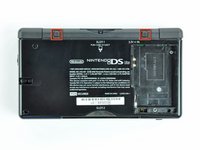
Unscrew the Phillips screw securing the battery cover to the lower case.
-
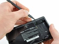
Pry the battery cover upward with a spudger or fingernail, and lift out of the lower case.
 Ask FixBot
-
-
-
Wedge the edge of a spudger in between the side of the battery and the lower case housing and pry upward to dislodge the battery.
-
Remove the battery from the DS Lite.
-
-
-
-
-
Use the tip of a spudger to pry both rubber feet off the DS Lite.
-
-
-
Remove the following screws securing the lower case to the body of the DS Lite:
-
Two 4.3 mm gold Phillips screws
-
One 3.9 mm black Tri-point screw
-
One 3.3 mm silver Phillips screw
-
Three 5.5 mm silver Tri-point screws
-
-
-
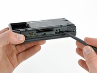
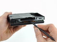
Insert the edge of a spudger in between the lower and upper case near the top right corner of the DS Lite.
-
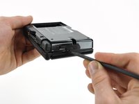
Carefully run the spudger along the right edge of the DS Lite, creating an opening in the process.
-
Continue running the spudger along the backside of the DS Lite until the majority of the lower case has been separated from the upper case.
-
-
-
-
-
-
Use the flat edge of a spudger to pry the Wi-Fi antenna connector straight up from its socket on the Wi-Fi board.
-
-
-
Use the flat edge of a spudger to pry the Wi-Fi board connector straight up from its socket on the motherboard.
-
-
-
Use the flat edge of a spudger to separate the right edge of the Wi-Fi board from the motherboard.
-
Remove the Wi-Fi board from the DS Lite.
-
-
-
-
-
Use the flat edge of a spudger to pry the microphone connector straight up from its socket on the motherboard.
-
-
-
Position the antenna cable with its connector facing up and away from the motherboard using a spudger to hold it down lightly in the gap between chips on the motherboard.
-
Slowly and carefully pull the antenna cable until the cable connector is under the DS Lite game cartridge reader.
-
Continue pulling the cable until the cable connector comes out from under the game cartridge reader on the right side.
-
-
-
Use your fingernail or the edge of a spudger to carefully flip up the touchscreen ribbon cable retaining flap.
-
Use the tip of a spudger to pull the touchscreen ribbon cable straight out of its socket.
-
-
-
-
Remove the two 3.4 mm Phillips screws securing the motherboard to the upper case.
-
-
-
Open the display enough to use your finger to push the front edge of the motherboard up and away from the upper case.
-
-
-
Use your fingernail or the flat edge of a spudger to carefully flip up the upper LCD ribbon cable retaining flap.
-
Pull the motherboard away from the DS Lite to separate the upper LCD ribbon cable from its socket on the motherboard.
-
Remove the motherboard from the DS Lite.
-
Now you may open the retaining flap for the lower LCD screen in the same way and separate the lower LCD screen from the motherboard.
-
-
-
-
-
-
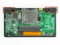
The power button is located in the upper right corner of the logic board, directly behind the right bumper.
-
-
-
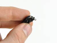
The power button is attached to the PCB with six solder points. There are also two plastic pegs located underneath the power button.
-
To prepare, you should first add some fresh solder to each of the six solder joints.
-
To desolder, hold the desoldering wick between the solder joint and the soldering iron, and press the iron onto the wick for a few seconds until it turns silver.
-
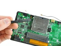
You can use tweezers to check if the individual pins are properly desoldered. To do this, press the tweezers against the side of the pin and see if it moves.
-
-








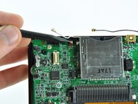


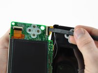
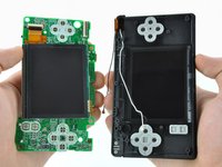


Follow the steps in reverse order to reassemble your device.
Cancel: I did not complete this guide.
One other person completed this guide.