Introduction
This guide will instruct you in proper cellphone disassembly and removal of the faulty logic board for replacement.
What you need
-
-
-
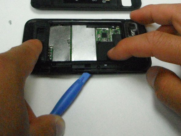
Wedge the opening tool in-between the back cover and the body of the phone in the opening denoted by the arrow.
 Ask FixBot
-
-
-
Once wedged in the opening, slide the opening tool around the side of the phone and remove the back cover, setting it aside.
-
-
-
Insert the opening tool between the battery and the battery holder and wedge the battery out.
-
-
-
Open the plastic cover with your finger to expose the SD card.
-
Use the opening tool to grab the edge of the SD card and pull it straight out.
-
-
-
-
Wedge the plastic opening tool in-between the plastic layer and the front cover.
-
-
-
Carefully separate the bottom piece from the top plastic piece.
-
Disconnect the ribbon cable connecting the display to the logic board by firmly pulling the cable straight outward.
-
The screen can now be removed.
-
-
-
Separate the logic board and the display cover from the back cover and orient the logic board so the camera faces toward you.
-
Disconnect the back cover by wedging the plastic opening tool in between the motherboard and the connector and prying outward.
-
-
-
Flip the logic board and display cover over so the camera faces away from you.
-
Bend the two halves of the device away from you to pry the final ribbon connector off the logic board.
-
-




To reassemble your device, follow these instructions in reverse order.
Cancel: I did not complete this guide.
2 other people completed this guide.

2 Guide Comments
Imbecells give up DEMONIC HOLD PRAISE THE LORD HE HAS COME 4 U
idoits have faith like a lil ole mustard seed
