Introduction
To remove the lens is to teardown the whole device. Everything must come apart to remove the lens and its adaptor from the top of the dome.
What you need
-
-
The MTW100 is composed of four stages, one built on top of the other:
-
The base
-
The speaker chamber
-
The radiator
-
The head
 Ask FixBot
-
-
-
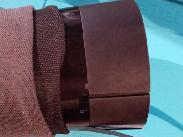
The base can be accessed by first removing the rubber band on which the Meeting Owl sits. It is simply glued, so it can be removed without any special tool.
-
Once removed, it gives access to four Phillips screws retaining the base to the rest of the device.
-
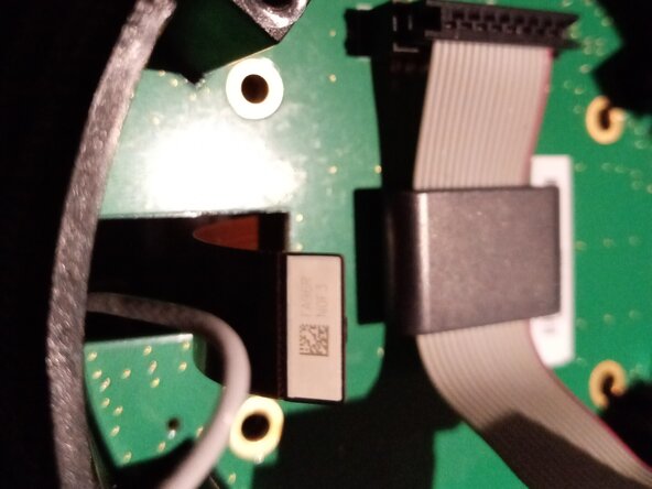
When opening the base, be aware of the ribbon cable and the cables connecting the speaker.
-
-
-
The speaker can be disconnected by simply pulling off the connector from the PCB.
-
The ribbon cable, providing power and carrying the data between the USB port and the Qualcomm CPU, is retained by a latch connector. Using tweezers or the tip of a plastic stick, flip up the latch to release the ribbon cable.
-
-
-
The control buttons are simply slid one on top of the other. Remove them to see the whole PCB.
-
Here is the PCB from a few different angles.
-
-
-
The LED ring allows the LEDs on the base PCB to shine! Even though it technically completes the base stage, it is screwed to the bottom of the speaker chamber.
-
To completely expose the ring, the double black sheathing covering the device has to be pulled up toward the head.
-
Four Phillips screws have to be removed to free the ring.
-
-
-
The speaker chamber is composed of a cone at the bottom, a speaker and a housing cover. The cone allows the sounds to be spreaded uniformly in all directions. It can be separated by removing four Phillips screws.
-
Once separated, be cautious of how the ribbon cable and the speaker cable go through the cone
-
-
-
Here again, the speaker is maintained by four Phillips screws. Remove them to be able to gently pull the speaker from the housing.
-
-
-
-
Yet again, four Phillips screws need to be removed at the bottom to release the housing.
-
When removing the housing, the ribbon cable will need to be pulled off gently to unglue it.
-
-
-
The radioator stage sits against the CPU housing located on the other side in the device's head. Its main function is to cool down the CPU. It is made of metal and is pretty heavy compared to the previous stages. With the lens, it is what gives the MTW100 most of its weight.
-
Remove the four Phillips screws to be able to remove it. As said, it sits against the CPU housing, but it is not glued to it. You will have no problem removing the radiator.
-
-
-
The head contains the CPU, the camera sensor and the lens in that order. The CPU sits on its own PCB where the ribbon cable connects, as does the antenna.
-
The PCB isn't held by anything. However, before removing it, the antenna and the camera sensor must be disconnected. Simply pull them off.
-
Then, gently pull off the PCB to dislodge it. The easiest pulling point is at the opening for the antenna and the camera sensor.
-
-
-
To access the CPU, memory and storage, the thermal pad first needs to be removed. Under it, there is a metal lid that is clipped on a metal lip under it.
-
At each of the four corners, there is a small opening where the tip of a tweezer can be inserted to pull delicately the lid.
-
Note : there are thermal pads over some of the components. They may be sticked to the lid or to the component, just be sure to not loose them.
-
-
-
The main compartment
-
The biggest component is the Qualcomm 410E CPU (top left). Partnumber APQ8016.
-
At its side sits the Kingston memory component (top right), which contains both an eMMC and RAM. Partnumber 08EMCP08-NL3DT227.
-
In the same compartment, there is the Qualcomm power management integrated circuit (PMIC) (bottom right). Partnumber PM8916.
-
The small compartment
-
Here sits a specialized IC for the wireless communication by Qualcomm. Partnumber WCN3660B.
-
-
-
There is nothing special around the CPU, only resistors and capacitors.
-
There a two test points visible with no specific naming.
-
-
-
The Kingston memory component 2400642-002 is an embedded Multi-Chip Package (eMCP) combining 8GB eMMC (TLC) flash storage with 8Gb LPDDR3 SDRAM.
-
-
-
The Qualcomm PM8916 is a power management IC. It is surrounded by a few inductors, capacitors, resistors and what looks like a crystal.
-
-
-
The WCN3660B provides Bluetooth and wifi connections. The IC is surrounded by capacitors, resistors, a crystal and two filters (unidentified FL1 and FL3 seems to be labelled "de ORN").
-
-
-
The PCB will still be held by another ribbon cable linking it to a different PCB responsible of lighting the Meeting Owl's eyes. Disconnect the cable to release completely the CPU's PCB.
-
Here can be seen both sides of the CPU's PCB.
-
-
-
The second PCB is responsible of lighting the Meeting Owl's eyes. It is retained by four torx screws. Use a T9 head to remove them.
-
Then, simply remove the PCB by gently pulling it off once again by the antenna and sensor cable opening.
-
-
-
Behind the second PCB is a metal retainer. The camera sensor is sticked by a thermal pad against that metal retainer.
-
Removing the retainer reveals the sensor glued to the lens adaptor.
-
Initially, the metal retainer had been removed and the sensor was still glued to the lens adaptor. The sensor was then separated from the lens adaptor by pushing against one of its corner.
-
In the picture, the camera sensor was reseated on the blue thermal pad of the metal retainer. The lens and its adaptor are visible in the last picture.
-
-
-
Four screws prevent the lens and its adaptor from pivoting and being removed. Removing the four Phillips screws allow to pivot the lens adaptor by 90 degrees and to push it through the head's dome.
-
Beware not to drop the lens when removing it from the head.
-
The last picture is from a broken lens. It was broken in the transport, nothing to do with it having been dropped when removing it from the head's dome.
-
-
-
The lens and the adaptor are kept together by two means. For one, the base of the lens is threaded and screwed into the adaptator. Second, they are glued together by what looks like hot glue applied at their junction (not visible on the pictures since it had already been removed).
-
To separate them, the glue must first be removed. Simply slide a sharp tool behind the glue and slowly pry it. Take care to not cause damage to the lens and its surrounding.
-
Then unscrew the lens from the adaptor.
-
-
-
Since the lens has no official replacement part, one must first find a "donor" Meeting Owl. The MTW100 and MTW200 share the same lens and can be used as donor.
-
However, the MTW100 and MTW200 don't have the same camera resolution (720p VS 1080p). So the lens, its adaptor and the sensor glued to it can't be simply swapped from one generation to the other. (it is unknow if a MTW200 sensor would work properly on a MTW100). The sensor must be pried off the adaptator by pushing one of its corner.
-
The good sensor can be glued back by putting a small amount of glue (super glue) at the junction of the sensor to the adaptor. However, one could choose to keep the sensor in place using the thermal pad on the metal retainer side.
-
And since the lens transplant will must likely result in an unfocused image, the MTW100 must be reassemble before correcting its focus. While displaying the video from the camera in your favorite app, slightly turn the metal ring around the lens clockwise or counter-clockwise to find the sweet spot where the image is the sharpest.
-
One could disassemble the whole device once more to glue back the lens to the adaptor. This will prevent loosing the focus again or completely removing the lens off from the Meeting Owl. However, knowing how to adjust the focus by rotating the lens from the top of the dome allows us to keep it as is.
-


To reassemble your device, follow these instructions in reverse order.