Free Shipping on Domestic Orders $75+

Mayflash F500 PCB Replacement

Views: 437

View statistics:

Past 24 Hours:
5
Past 7 Days:
37
Past 30 Days:
124
All Time:
437
Comments: 0

No one has left comments on this guide. Will you be first?

Go to guide comments
Completed: 0

No one has marked this guide "completed." Will you be the first?

Favorites: 0

No one has favorited (and subscribed to) this guide. Will you be the first?

Time Required: 15 minutes
Difficulty: Easy
Mayflash F500 PCB Replacement

Introduction

Go to step 1 ↓

The PCBs in the Mayflash F500 handle the headphone port and the menu controls with switches for the controller. If the switches are not working, or the headphone jack does not transmit audio, use this guide for replacing the PCBs inside the controller.

No background in circuit soldering or breadboard management required. Be sure to unplug the controller and any peripherals connected to it before opening this controller. As you are removing PCBs, make sure to keep careful track of orientation and location of the PCBs and wires that connect to them.

What you need

Tools

    1. Mayflash F500 PCB Replacement, PCB: step 1, image 1 of 3 Mayflash F500 PCB Replacement, PCB: step 1, image 2 of 3 Mayflash F500 PCB Replacement, PCB: step 1, image 3 of 3
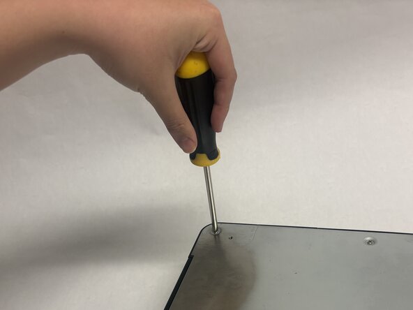
      • Remove the six Phillips screws on the bottom of the controller.

      Ask FixBot

      Add Comment

    2. Mayflash F500 PCB Replacement: step 2, image 1 of 3 Mayflash F500 PCB Replacement: step 2, image 2 of 3 Mayflash F500 PCB Replacement: step 2, image 3 of 3
      • Use a wedge tool between the metal plate and main body of the controller.

      • Fully lift the backplate to reveal the inside of the controller.

      Ask FixBot

      Add Comment

    3. Mayflash F500 PCB Replacement: step 3, image 1 of 3 Mayflash F500 PCB Replacement: step 3, image 2 of 3 Mayflash F500 PCB Replacement: step 3, image 3 of 3
      • Remove the cables connecting the buttons and joystick to the main PCB.

      • The cables connecting to the other three PCBs do not need to be removed.

      Ask FixBot

      Add Comment

    4. Mayflash F500 PCB Replacement: step 4, image 1 of 3 Mayflash F500 PCB Replacement: step 4, image 2 of 3 Mayflash F500 PCB Replacement: step 4, image 3 of 3
      • Remove the four screws from the main PCB.

      Ask FixBot

      Add Comment

    5. Mayflash F500 PCB Replacement: step 5, image 1 of 2 Mayflash F500 PCB Replacement: step 5, image 2 of 2
      • Remove the eight remaining screws on the other PCBs connected to the main PCB.

      Ask FixBot

      Add Comment

    6. Mayflash F500 PCB Replacement: step 6, image 1 of 3 Mayflash F500 PCB Replacement: step 6, image 2 of 3 Mayflash F500 PCB Replacement: step 6, image 3 of 3
      • Slowly lift the four PCBs out of the case.

      • For three of the PCBs, they have parts jutting outside of the case. Remove each PCB carefully to not damage the other components.

      Ask FixBot

      Add Comment

Conclusion

To reassemble your device, follow these instructions in reverse order.

Cancel: I did not complete this guide.

Howard (FGC)

Member since: 01/20/26

133 Reputation

1 Guide authored

Team

UC Davis, Team 2-5, Morris Winter 2026 Member of UC Davis, Team 2-5, Morris Winter 2026

UCD-MORRIS-W26S2G5

3 Members

12 Guides authored

0 Guide Comments

Add Comment

View Statistics:

Past 24 Hours: 5

Past 7 Days: 37

Past 30 Days: 124

All Time: 437