
Free Shipping on Domestic Orders $75+

Mac mini Late 2014 I/O Bezel Replacement

What you need

  1. Mac mini Late 2014 I/O Bezel Replacement, Bottom Cover: step 1, image 1 of 1
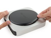
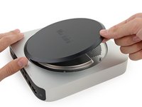
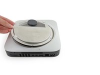
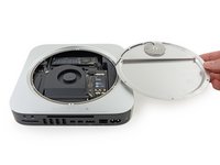
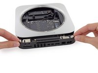
    • The bottom cover is clipped onto three screw posts.

    • Pry near, but not right on the screw posts.

    Ask FixBot

    Add Comment

  2. Mac mini Late 2014 I/O Bezel Replacement: step 2, image 1 of 3 Mac mini Late 2014 I/O Bezel Replacement: step 2, image 2 of 3 Mac mini Late 2014 I/O Bezel Replacement: step 2, image 3 of 3
    • Use the plastic opening tool to pry the bottom cover up off of the Mac mini.

    Ask FixBot

    Add Comment

  3. Mac mini Late 2014 I/O Bezel Replacement: step 3, image 1 of 2 Mac mini Late 2014 I/O Bezel Replacement: step 3, image 2 of 2
    • Lift and remove the bottom cover.

    Ask FixBot

    Add Comment

  4. Mac mini Late 2014 I/O Bezel Replacement, Antenna Plate: step 4, image 1 of 1
    • Remove the following TR6 screws from the antenna plate:

    • Three 4.1 mm screws

    • Three 1.9 mm screws

    Ask FixBot

    Add Comment

  5. Mac mini Late 2014 I/O Bezel Replacement: step 5, image 1 of 2 Mac mini Late 2014 I/O Bezel Replacement: step 5, image 2 of 2
    • Do not completely remove the antenna plate; it is still connected to the Mac mini by an antenna cable.

    • With the I/O ports facing you, flip the antenna plate to the right to allow access to the antenna cable connector.

    Ask FixBot

    Add Comment

  6. Mac mini Late 2014 I/O Bezel Replacement: step 6, image 1 of 1
    • Remove the single 3.4 mm T6 screw and washer from the antenna cable.

    • Be careful not to lose the washer when removing the screw.

    Ask FixBot

    Add Comment

  7. Mac mini Late 2014 I/O Bezel Replacement: step 7, image 1 of 2 Mac mini Late 2014 I/O Bezel Replacement: step 7, image 2 of 2
    • Use the point of a spudger to lift the antenna connector straight up off its socket on the airport card.

    Ask FixBot

    Add Comment

  8. Mac mini Late 2014 I/O Bezel Replacement: step 8, image 1 of 2 Mac mini Late 2014 I/O Bezel Replacement: step 8, image 2 of 2
    • Carefully pull the antenna cable out from the gap between the power supply and case.

    Ask FixBot

    Add Comment

  9. Mac mini Late 2014 I/O Bezel Replacement: step 9, image 1 of 1
    • Remove the antenna plate from the Mac mini.

    Ask FixBot

    Add Comment

  10. Mac mini Late 2014 I/O Bezel Replacement, Fan Assembly: step 10, image 1 of 1
    • Remove the two 12 mm T6 screws from the fan.

    • Loosen the 27 mm T6 captive screw–it will get removed with the fan assembly.

    Ask FixBot

    Add Comment

  11. Mac mini Late 2014 I/O Bezel Replacement: step 11, image 1 of 3 Mac mini Late 2014 I/O Bezel Replacement: step 11, image 2 of 3 Mac mini Late 2014 I/O Bezel Replacement: step 11, image 3 of 3
    • The fan connector is trapped under the edge of the fan and cannot be disconnected until the fan is moved.

    • Do not attempt to remove the fan entirely.

    • Lift the fan straight up to free the captive screw from its hole in the logic board.

    • Pull the fan away from the SSD until you can easily access the fan connector.

    Ask FixBot

    Add Comment

  12. Mac mini Late 2014 I/O Bezel Replacement: step 12, image 1 of 2 Mac mini Late 2014 I/O Bezel Replacement: step 12, image 2 of 2
    • Use the point of a spudger to lift the fan connector straight up out of its socket on the logic board.

    Ask FixBot

    Add Comment

  13. Mac mini Late 2014 I/O Bezel Replacement: step 13, image 1 of 1
    • Remove the fan from the Mac mini.

    Ask FixBot

    Add Comment

  14. Mac mini Late 2014 I/O Bezel Replacement, Logic Board Assembly: step 14, image 1 of 1
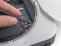
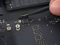
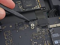
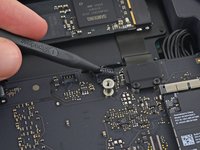
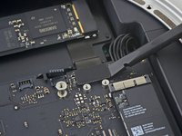
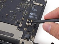
    • Remove the 2.6 mm T6 screw securing the SATA cable connector bracket.

    Ask FixBot

    Add Comment

  15. Mac mini Late 2014 I/O Bezel Replacement: step 15, image 1 of 2 Mac mini Late 2014 I/O Bezel Replacement: step 15, image 2 of 2
    • Remove the SATA cable connector bracket.

    Ask FixBot

    Add Comment

  16. Mac mini Late 2014 I/O Bezel Replacement: step 16, image 1 of 2 Mac mini Late 2014 I/O Bezel Replacement: step 16, image 2 of 2
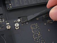
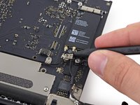
    • Use the flat end of a spudger to lift the SATA cable connector up off of its socket on the logic board.

    Ask FixBot

    Add Comment

  17. Mac mini Late 2014 I/O Bezel Replacement: step 17, image 1 of 2 Mac mini Late 2014 I/O Bezel Replacement: step 17, image 2 of 2
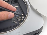
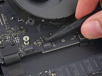
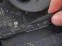
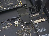
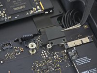
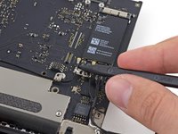
    • Use the tip of a spudger to disconnect the IR sensor cable connector by prying it straight up from its socket.

    Ask FixBot

    Add Comment

  18. Mac mini Late 2014 I/O Bezel Replacement: step 18, image 1 of 1
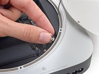
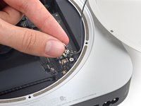
    • The following three steps only apply to Mac minis equipped with a PCIe SSD. Skip the next three steps if your Mac mini only has a hard drive.

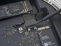
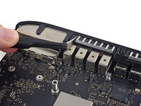
    • Remove the two 2.6 mm T6 screws securing the PCIe SSD cable bracket.

    Ask FixBot

    Add Comment

  19. Mac mini Late 2014 I/O Bezel Replacement: step 19, image 1 of 2 Mac mini Late 2014 I/O Bezel Replacement: step 19, image 2 of 2
    • Remove the PCIe SSD cable bracket.

    Ask FixBot

    Add Comment

  20. Mac mini Late 2014 I/O Bezel Replacement: step 20, image 1 of 2 Mac mini Late 2014 I/O Bezel Replacement: step 20, image 2 of 2
    • Lift the PCIe SSD connector up off its socket.

    Ask FixBot

    Add Comment

  21. Mac mini Late 2014 I/O Bezel Replacement: step 21, image 1 of 1
    • Remove the single 16 mm T6 screw securing the logic board.

    Ask FixBot

    Add Comment

  22. Mac mini Late 2014 I/O Bezel Replacement: step 22, image 1 of 1
    Tool used on this step:
    Mac mini Logic Board Removal Tool
    $4.99
    Buy
    • To remove the logic board, the two cylindrical rods of the Mac mini Logic Board Removal Tool must be inserted into the holes highlighted in red. Inserting instruments into any logic board holes other than the ones highlighted in red may destroy the logic board.

    • Insert the Mac mini Logic Board Removal Tool into the two holes highlighted in red. Be sure the rods make contact with the case under the logic board before proceeding.

    Ask FixBot

    Add Comment

  23. Mac mini Late 2014 I/O Bezel Replacement: step 23, image 1 of 3 Mac mini Late 2014 I/O Bezel Replacement: step 23, image 2 of 3 Mac mini Late 2014 I/O Bezel Replacement: step 23, image 3 of 3
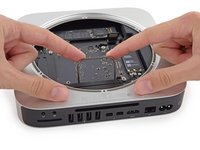
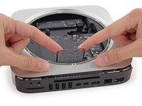
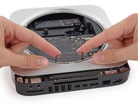
    • Carefully pull the tool toward the I/O board. The logic board and I/O board assembly should slightly slide out of the outer case.

    • Cease prying when the removal tool makes contact with the opening in the rear case.

    • Remove the Mac mini Logic Board Removal tool.

    Ask FixBot

    Add Comment

  24. Mac mini Late 2014 I/O Bezel Replacement: step 24, image 1 of 2 Mac mini Late 2014 I/O Bezel Replacement: step 24, image 2 of 2
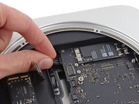
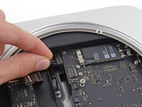
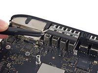
    • Pull the DC-In cable connector straight out of its socket on the logic board.

    Ask FixBot

    Add Comment

  25. Mac mini Late 2014 I/O Bezel Replacement: step 25, image 1 of 2 Mac mini Late 2014 I/O Bezel Replacement: step 25, image 2 of 2
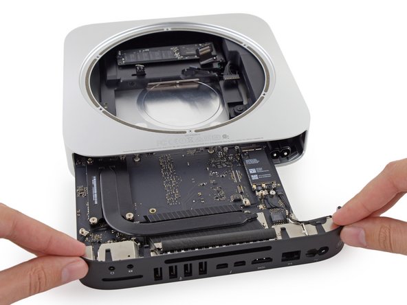
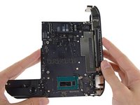
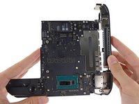
    • Carefully slide the logic board assembly out of the Mac mini, minding any cables that may get caught.

    Ask FixBot

    Add Comment

  26. Mac mini Late 2014 I/O Bezel Replacement, Heat Sink: step 26, image 1 of 2 Mac mini Late 2014 I/O Bezel Replacement, Heat Sink: step 26, image 2 of 2
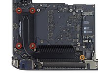
    • Remove the following screws securing the heat sink to the logic board:

    • Four 8.6 mm T8 Torx screws

    • One 2.9 mm T6 Torx screw

    • Be careful not to lose the springs held beneath each of the T8 heat sink screws, they may fall off of the screws as you remove them.

    • During reassembly, tighten these screws evenly to ensure the heat sink stays flat against the CPU.

    Ask FixBot

    Add Comment

  27. Mac mini Late 2014 I/O Bezel Replacement: step 27, image 1 of 3 Mac mini Late 2014 I/O Bezel Replacement: step 27, image 2 of 3 Mac mini Late 2014 I/O Bezel Replacement: step 27, image 3 of 3
    • Remove the heat sink from the logic board.

    • If the heat sink appears to be stuck to the logic board after removing all screws, it may be helpful to use a spudger to separate the two components.

    • Don't reassemble your Mac mini without applying a new layer of thermal paste.We have a thermal paste guide to show you how.

    Ask FixBot

    Add Comment

  28. Mac mini Late 2014 I/O Bezel Replacement, I/O Bezel: step 28, image 1 of 1
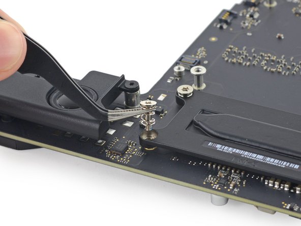
    • Remove the following T6 Torx screws from the I/O port antenna cables:

    • Three 2.8 mm screws with washers

    • One 3.4 mm screw

    • One 2.7 mm screw

    Ask FixBot

    Add Comment

  29. Mac mini Late 2014 I/O Bezel Replacement: step 29, image 1 of 2 Mac mini Late 2014 I/O Bezel Replacement: step 29, image 2 of 2
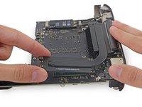
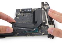
    • Use the point of a spudger to lift the power switch cable connector straight up out of its socket on the logic board.

    Ask FixBot

    Add Comment

  30. Mac mini Late 2014 I/O Bezel Replacement: step 30, image 1 of 3 Mac mini Late 2014 I/O Bezel Replacement: step 30, image 2 of 3 Mac mini Late 2014 I/O Bezel Replacement: step 30, image 3 of 3
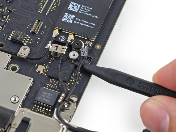
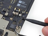
    • Use the point of a spudger to lift the antenna connectors up off of their sockets on the AirPort card.

    Ask FixBot

    Add Comment

  31. Mac mini Late 2014 I/O Bezel Replacement: step 31, image 1 of 1
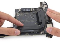
    • Remove the four 2.7 mm T6 Torx screws holding the I/O bezel to the logic board.

    Ask FixBot

    Add Comment

  32. Mac mini Late 2014 I/O Bezel Replacement: step 32, image 1 of 2 Mac mini Late 2014 I/O Bezel Replacement: step 32, image 2 of 2
    • Remove the foam bumper from between the I/O bezel and USB ports.

    Ask FixBot

    Add Comment

  33. Mac mini Late 2014 I/O Bezel Replacement: step 33, image 1 of 2 Mac mini Late 2014 I/O Bezel Replacement: step 33, image 2 of 2
    • Pull the I/O bezel off of the logic board, minding any cables that may get caught.

    • Try not to handle the small steel tabs on the logic board and I/O bezel, as oils from your fingers may cause interference issues. Before installing the logic board assembly, clean the metal tabs to remove any oils transferred during the removal process.

    Ask FixBot

    Add Comment

Conclusion

To reassemble your device, follow these instructions in reverse order.

Cancel: I did not complete this guide.

3 other people completed this guide.

Sam Goldheart

Member since: 10/18/12

477,615 Reputation

538 Guides authored

Team

iFixit Member of iFixit

Staff

122 Members

26,593 Guides authored

1 Guide Comment

Removing the I/O Bezel does not require the removal of the heatsink, so I have edited the guide to reflect as much. This makes the process much less complex.

Liam W - Reply Share

Add Comment

View Statistics:

Past 24 Hours: 1

Past 7 Days: 12

Past 30 Days: 53

All Time: 8,262