
Logitech G Pro Wireless Mouse Side Button Switch Replacement

Shane Guzman and 3 other contributors
Last updated on Jun 15, 2026
Views: 2.2K
View statistics:
- Past 24 Hours:
- 32
- Past 7 Days:
- 217
- Past 30 Days:
- 827
- All Time:
- 2,236
Comments: 0
No one has left comments on this guide. Will you be first?
Go to guide commentsCompleted: 1 2
1 person has marked this guide "completed." Will you be next?
2 people have marked this guide "completed." Including you — great job!
Favorites: 0 1
No one has favorited (and subscribed to) this guide. Will you be the first?
1 person has favorited (and subscribed to) this guide — and that's you!
Introduction
Go to step 1 ↓This guide shows the step by step replacement of a Logitech G Pro Wireless mouse side button from disassembly to replacement to reassembly.
Required tools:
- Soldering Iron Kit
- Spudger
- Tweezers
- Phillips #00 screwdriver
SAFTEY WARNING: THIS GUIDE USES A SOLDERING IRON WHICH CAN CAUSE SEVERE BURNS OR START FIRES. IF YOU DO NOT HAVE EXPERIENCE WITH USING A SOLDERING IRON, FIND SOMEONE WHO HAS PROPER EXPERIENCE SOLDERING OR RESEARCH AND LEARN ABOUT SOLDERING IRONS AND HOW TO PROPERLY USE THEM PRIOR TO STARTING THIS GUIDE. ONLY SOLDER IN A WELL VENTILATED AREA FREE FROM HIGHLY FLAMMABLE MATERIAL. USE WITH EXTREME CAUTION.
What you need
Tools
-
-
Spudger4.9
-


-
-
-
Find a stable desk or table to work on.
-
Create a clean work area on the surface.
-
Set up a mat on the work area.
-
Place the mouse on the work area.
 Ask FixBot
-
-
-
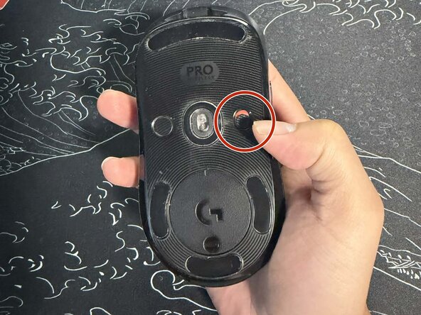
Remove the seven 4.4 mm-long Phillips #00 screws on the bottom shell of the mouse.
-
-
-
Separate the bottom shell of the mouse from the top shell.
-
Remove the single 3 mm-long Phillips #00 screw securing the battery bracket.
-
Pop the battery out gently with the spudger.
-
-
-
Use the tweezers to lift up the electrical ribbon locking tab.
-
Gently pull out the ribbon to separate the bottom shell and top shell of the mouse.
-
-
-
Remove the four 3 mm-long Phillips #00 screws securing the left and right mouse buttons on the inside of the top shell.
-
-
-
Using the screwdriver, remove the two 3 mm-long Phillips #00 screws securing the middle housing assembly inside the mouse. Set the screws aside in a safe place to avoid losing them.
-
Using the spudger, gently pry up the middle housing assembly from the edges. Carefully lift the middle section out of the mouse body.
-
-
-
Using the screwdriver, remove the four 3 mm-long Phillips #00 screws securing the scroll wheel assembly to the mouse.
-
Using the spudger, gently lift the small ribbon cable connector from the circuit board. Carefully disconnect the ribbon cable by pulling it straight out of the connector.
-
Once disconnected, lift and remove the scroll wheel assembly from the mouse.
-
-
-
-
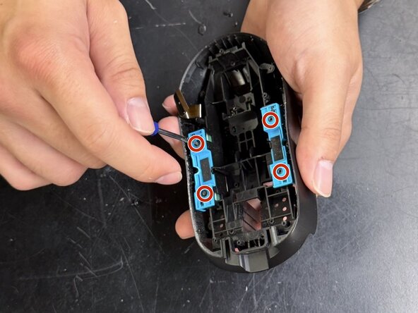
Using the screwdriver, remove the four 3mm Phillips #00 screws securing the blue side button brackets on both sides of the mouse.
-
Remove the nine 3 mm-long Phillips #00 screws securing the main internal frame (black plastic structure).
-
Remove the single 3mm Phillips #00 screw at the top of the mouse near the front end.
-
-
-
Carefully lift the internal assembly out of the outer mouse shell. Set the outer shell aside.
-
Remove the blue side button brackets from both sides of the internal frame.
-
Gently lift out the four side buttons from the frame.
-
-
-
Using the spudger, gently pry up the edge of the side circuit board from the plastic frame. Work your way along the edge, carefully releasing the clips holding the board in place.
-
Once loosened, lift the side circuit board away from the frame.
-
-
-
Using the spudger, gently insert the tip under the edge of the circuit board. Carefully pry upward to separate the board from the adhesive securing it to the frame.
-
Continue working along the edges until the adhesive is fully released. Once loosened, lift the circuit board assembly away from the frame.
-
-
-
Desolder the switch pins on the underside of the PCB.
-
Using the spudger, gently insert the tip underneath the side switch component. Carefully lift the edge of the switch to begin separating it from the board.
-
Use a second tool (such as tweezers or a flathead tool) to assist in prying the switch upward. Continue applying gentle pressure until the side switch is fully detached from the board.
-
-





To reassemble your device, follow the above steps in reverse order.
Take your e-waste to an R2 or e-Stewards certified recycler.
Repair didn’t go as planned? Try some basic troubleshooting or ask our Answers community for help.
Cancel: I did not complete this guide.
One other person completed this guide.
Team

CSU Los Angeles, Team 4-13, Harris Spring 2026 Member of CSU Los Angeles, Team 4-13, Harris Spring 2026
CSULA-HARRIS-S26S4G13
3 Members
12 Guides authored
