
Lenovo Y410P LCD Replacement

Brandon and 5 other contributors
Last updated on Mar 9, 2019
Views: 6.3K
View statistics:
- Past 24 Hours:
- 2
- Past 7 Days:
- 24
- Past 30 Days:
- 107
- All Time:
- 6,341
Comments: 2
2 comments on steps.
Completed: 8 9
8 people have marked this guide "completed." Will you be next?
9 people have marked this guide "completed." Including you — great job!
Favorites: 0 1
No one has favorited (and subscribed to) this guide. Will you be the first?
1 person has favorited (and subscribed to) this guide — and that's you!
Slice and Dice
The steps in this guide should be split up and made into a series of prerequisite guides.
Needs Better Images
Better photos will improve this guide. Help out by taking, editing, or uploading new ones!
Missing Steps
Oops! This guide is currently missing one or more important steps.
Introduction
Go to step 1 ↓This guide will help you replace a broken LCD.
What you need
Tools

-
-
-
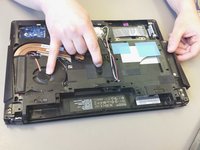
Remove eight M2.5 x 8mm Phillips head screws, using a Phillips #0 screwdriver, in the specified locations.
-
Lift the bottom cover off and set it aside.
 Ask FixBot
-
-
-
Remove the two M2.5x4mm screws using a Phillips #0 screwdriver.
-
Slide the hard drive out of the casing.
-
-
-
With the laptop's bottom facing up, pull the optical drive release lever back and pull the optical drive out.
-
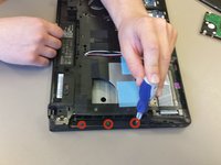
Unscrew the three M2x3mm Phillips head screws shown.
-
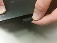
At the front edge of the laptop, empty the SD card holder by pressing on the card. This will allow for further disassembly in later steps.
-
-
-
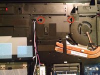
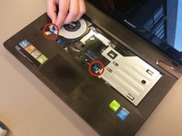
Remove the two M2.5 x 6mm screws using a Phillips #00 screwdriver.
-
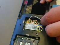
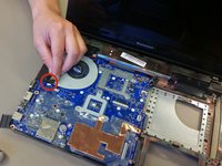
Disconnect the two WiFi antenna cables.
-
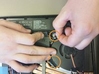
Disconnect the sound connector.
-
-
-
-
Open the laptop hinge. Tip the laptop onto its side, and use the back end of the screwdriver to push the keyboard out from the optical drive area.
-
Turn the laptop right side up and pry the keyboard up slowly, until it is clear of the case.
-
Detach the ribbon cables by opening the specified latches.
-
-
-
Detach the ribbon cables by opening the specified latches.
-
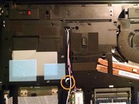
Turn the laptop upside down and remove the M2.5x8mm screw with Phillips #0 screwdriver.
-
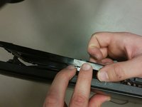
Turn the laptop on its side and pry the bottom from the top.
-
Remove the ribbon cable by opening its respective latch.
-
-
-
Remove the specified cable on top of the motherboard.
-
Flip the laptop over, and remove the specified cables.
-
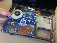
Remove the two M2.5x4mm screws with a Phillips #0 screwdriver
-
Remove the motherboard with hands.
-
-
-
-
-
Detach the LCD assembly by unscrewing four M2.5x4mm Phillips Screws. (Two on each side).
-
Pull the LCD assembly away from main frame.
-
-
-
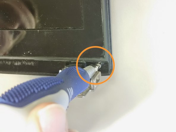
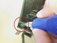
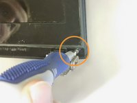
Using a flat head screwdriver, wedge out two plastic tabs to reveal the screws.
-
One tab is in the bottom left corner and one is in the bottom right corner. Symmetrical locations.
-
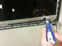
Using a #0 phillips screwdriver, unscrew two silver M2.5x4mm screws.
-
These are located underneath the previously removed plastic tabs.
-
-
-
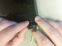
Unclip the latches at each bottom corner. They are located below the screws that were previously removed.
-
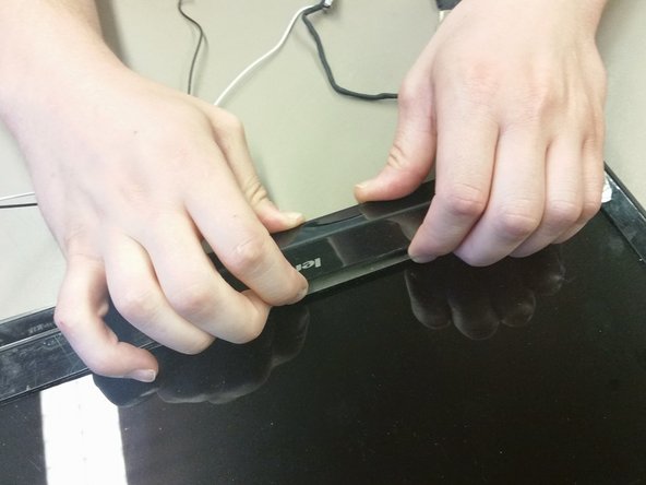
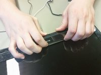
Place your fingers inside of the edge of the bezel. Separate the bezel by pulling it away from the back cover. Pull until one side has been lifted.
-
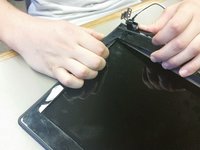
Use the same technique to separate all remaining sides of the bezel.
-
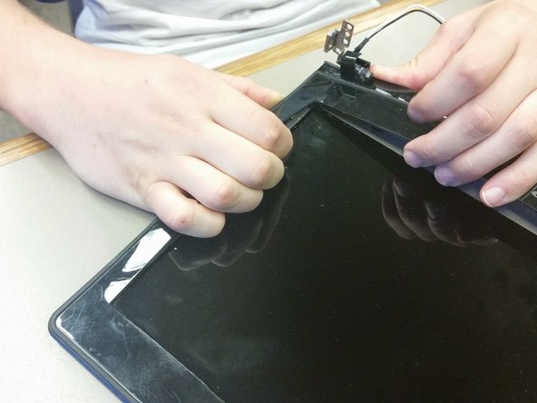
Starting at one corner and making your way around. Ensure the bezel is completely removed from the back cover.
-
Completely remove bezel from LCD screen and back cover.
-
-
-
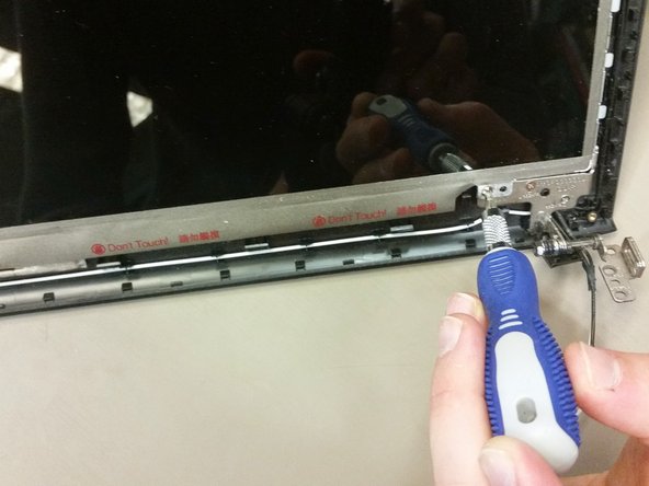
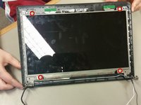
Unscrew the four M2.5x4mm Phillips screws. One screw is located at each corner.
-
-
-
Gently lift the LCD screen and flip it over.
-
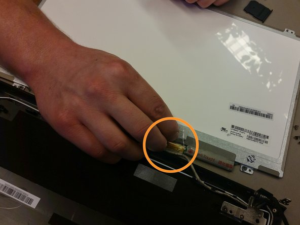
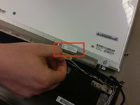
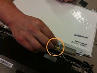
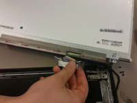
On back of the LCD screen, locate the protective tape in the bottom right corner. Peel off the tape to reveal a latch with a connector cable.
-
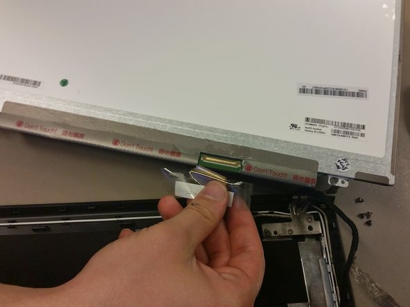
Flip the latch so that the connector cable can be removed. Remove the connector cable by pulling downwards.
-
The old LCD is now completely disconnected and you are ready to install a new LCD screen.
-
-













To reassemble your device, follow these instructions in reverse order.
Cancel: I did not complete this guide.
8 other people completed this guide.

Team

Cal Poly, Team 21-21, Maness Winter 2015 Member of Cal Poly, Team 21-21, Maness Winter 2015
CPSU-MANESS-W15S21G21
4 Members
72 Guides authored
