This translation was generated by a machine and has not been reviewed by a person yet. Speak this language? Review it.
Introduction
Here I explain how I replaced the factory thermal paste on the CPU and GPU of my Legion Legion Pro 7 16IAX10H with PTM7950 or Thermal Grizzly PTM Sheet, and what you need to consider when doing so.
Important: You need putty (e.g., from Thermal Grizzly). This is required for the VRAMs, as the factory heat sink uses putty there rather than thermal pads. Thermal pads are too thick and will prevent contact between the GPU die and the heat sink! For cleaning, you will need isopropyl alcohol and cotton swabs.
It is best to read through the guide once briefly before beginning the work. I recommend taking a photo once the laptop is open to have a reference for how everything looked before, in case you are unsure.
Also important: Without the replacement battery connected, the firmware will massively throttle the device's performance. For performance tests, the replacement battery must be connected!!!
Once you have replaced the factory paste with PTM, it takes a while for the PTM to optimally bond with the die and the heat sink. Typically, this takes about 12 thermal cycles, where the PTM must be heated to at least 65°C and then cool down completely. After that, optimal temperature values can be expected.
-
-
-
Use a JIS #1 screwdriver to remove the ten screws securing the bottom cover.
-
The six 12 mm M2 screws are located along the sides and front edge.
-
The four 4 mm M2 screws are located near the clutch hinges.
-
Keep the two sets of screws separate.
 Ask FixBot
-
-
-
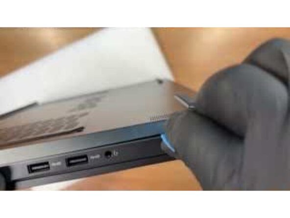
Insert an opening pick into the gap between the bottom cover and the housing along the left edge.
-
Slide the opening pick along the edge to release the clips.
-
Continue to release the clips in the hinge area, along the front edge, and along the right edge of the housing.
-
-
-
Lift the loosened bottom cover from the housing.
-
-
-
Pull the replacement battery plug straight out of its socket on the motherboard.
-
-
-
-
Remove the two screws securing the replacement battery.
-
Lift the replacement battery out of the housing.
-
-
-
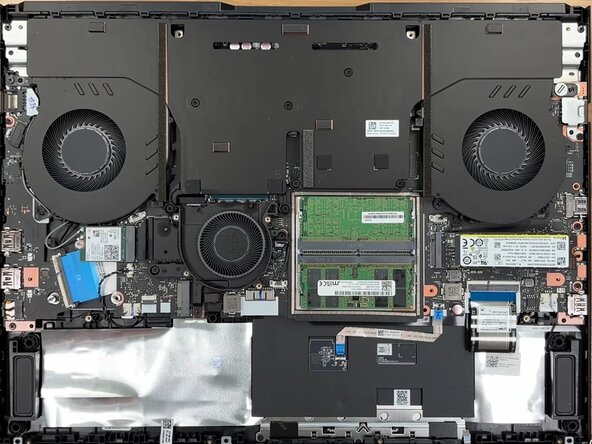
Use a JIS #00 screwdriver to remove the four small screws securing the cover to the center cooling fan.
-
Loosen the seven numbered captive screws in order from 1 to 7.
-
Release the cover from the two alignment pins and lift it off.
-
-
-
-
-
From this point on, it is very important that the battery is unplugged, or even better, completely removed, in order to prevent any potential short circuits and damage during the work as much as possible!!!
-
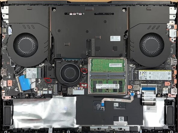
Next, we remove the chipset heat sink, which also cools two GPU VRAMs, by removing the marked screws and unplugging the power connector for the cooling fan. This would otherwise be the official Lenovo guide for removing the heat sink: https://support.lenovo.com/ch/de/documen...
-
The cooling fan can now be removed.
-
-
-
Remove the main heatsink for the CPU and GPU. This is the official guide from Lenovo: https://support.lenovo.com/ch/de/documen...
-
It is important to note the numbering of the screws and release them slowly in reverse order. Start from No. 7 down to No. 1. Release each screw only a little bit, and perform the sequence from 7 - 1 twice, with a third check-pass.
-
Note: First remove the two power connectors for the cooling fans. This is best done with your fingernails. Then, unplug the cable for the Wi-Fi antennas on the left side (marked in yellow in the image) from the Wi-Fi module and unthread it from the cooling fan.
-
Then remove the screws on the far left and far right (red markings). One screw is covered by a small Lenovo sticker. Removing it may void the warranty!
-
The heatsink can then be removed. It may be stuck a bit.
-
It is important to wiggle it slowly from all sides—left, right, and front near the RAM—to detach it. Avoid unnecessary pressure to prevent damaging or bending the vapor chamber.
-
-
-
Once the heat sink is removed, everything must be cleaned. Thermal pads can potentially be reused. However, the VRAM of the GPU as well as the GPU and CPU die must be cleaned with isopropyl alcohol. The same applies to the heat sink. Clean everything thoroughly there as well.
-
It is best to work with cotton swabs and clean everything thoroughly; avoid touching surfaces with your fingers or wear gloves.
-
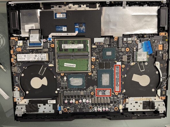
After cleaning, a small bead of thermal putty can be applied to each of the marked VRAM modules. Spread it slightly with the scraper. Not too much and not too little.
-
Then, cut the PTM7950 or Thermal Grizzly phase sheet PTM to size for the CPU and apply it. Tip: cut it to size, peel off the protective film on the first side of the PTM, then position the PTM on the CPU die and press it down. Then wait for 1 minute so that the PTM cools down from your fingers. This makes it easier to remove the second protective film.
-
Perform the same procedure for the GPU.
-
Then, perform a final check to ensure that no thermal pad has fallen off the heat sink on the voltage regulator modules (VRM) or the MOSFETs, and then reattach the heat sink.
-
Proceed carefully, position the heat sink in the air, and only lower and press it down at the very end. Then, re-tighten the screws in the reverse order of how you removed them.
-
First, the two outer screws. One of them has a Lenovo sticker on it. Then, tighten the screws according to the numbering 1-7. Tighten them slowly and only a little at a time. Perform 2 passes for tightening and 1 check pass to ensure everything is seated.
-
-
-
Next, reconnect the connectors for the fans (do not forget this under any circumstances!!!!) and secure the cable for the Wi-Fi connection again on the side by the left heat sink and reattach it to the Wi-Fi card (caution, very delicate pins).
-
Then reattach the fan for the chipset and secure it with the two screws.
-
Reconnect the power connector for the fan.
-
Now perform a quick function test. Reinsert and connect the battery and secure it with one screw.
-
Now place the outermost cover back on temporarily (do not click it into place, just lay it on!).
-
Now turn the device over, connect it to power, and switch it on.
-
Start the device and run either a demanding game or CPU and GPU benchmarks. Monitor the temperature while doing so.
-
If the GPU temperatures are around 78–80°C and the CPU temperatures are 80–90°C, everything is fine.
-
-
-
The PTM is burned in during this test and bonds perfectly between the CPU/GPU die and the heat sink. Let this test run for about 10 minutes. Afterwards, shut down the system and disconnect it from the power supply. Also disconnect and remove the replacement battery.
-
If the test was successful (no throttling or excessive thermal values), then the rest of the device can be reassembled.
-
Important: for these tests, the replacement battery must be connected. Without the replacement battery, the system firmware massively throttles the GPU performance and no representative values will be produced!
-
-






Follow the steps in reverse order to reassemble your device.

