Introduction
The Klipsch Cinema 600 Soundbar has a documented history of internal power supply failures. This issue typically causes the unit to shut down unexpectedly or fail to power on entirely.
This guide outlines how to replace a dead factory power supply board with an aftermarket Noyito AC-to-DC Dual-Output Isolated Power Supply Module (24V 4A / 5V 1A). Because the aftermarket board uses a different physical footprint, using a 3D-printed adapter board is highly recommended. The adapter stabilizes the mass of the new power supply and prevents exposed electrical leads from shorting against the soundbar's metal chassis.
Custom 3D-Printed Brackets (Choose One)
- Option A: [Jinxation Klipsch Cinema 600 Sound Bar PSU Board Mount]
- Option B: [Printer570 Klipsch Power Supply Adapter Board] (Used in this guide)
Technical Specifications & Wiring Blueprints
⚠️ WARNING: Unplug the 120V AC power cord from the wall outlet before beginning. Do not work on live electronics unless you have explicit experience and knowledge of high-voltage mains.
Mainboard Wiring Configurations
Klipsch produced two distinct hardware versions of the Cinema 600 mainboard. You must physically inspect the text labels printed on your original green factory board before wiring the new power supply. Matching wire colors blindly without checking your specific board version can cross-wire 5V power into Ground, causing a permanent short circuit.
- Version 1 Labels:
STB= Red |VDD= White |GND= Black - Version 2 Labels:
STB= Red |VDD= Black |GND= White
Noyito 4-Port DC Terminal Blueprint
The aftermarket board features four output screw terminals DC1+, DC1-, DC2+, DC2-). Connect your factory wires according to this layout:
- 24V Speaker Circuit:
* Thick Red Wire → DC1+ (+24V)
* Thick Black Wire → DC1- (-24V / Ground)
- 5V Logic & Standby Circuit:
* Ground Circuit (1 Wire): Clamp your designated GND wire into DC2-.
* Standby Jumper (2 Wires Twisted): Tightly twist the raw copper ends of the STB wire and the VDD wire together. Clamp this twisted pair directly into DC2+.
-
-
-
Remove nineteen T15 Torx screws from the rear casing of the soundbar.
-
Remove five T15 Torx screws from the bottom panel.
-
Remove two 2.5 mm hex screws from the rear.
 Ask FixBot
-
-
-
Insert a plastic spudger or car trim tool into the seam between the front housing and rear cover. Gently pry the back cover away from the soundbar chassis.
-
Carefully separate the rear cover just enough to access the internal electronics. The power supply module is located on the left side of the soundbar when viewing the unit from the front.
-
-
-
Source your preferred adapter board file and 3D print it prior to starting the teardown. (Printer570's Printable model shown here).
-
Prep the adapter by inserting four M3 screws (3/4-inch or longer) into the board's unthreaded mounting standoffs.
-
Apply firm downward pressure while driving the screws to tap threads directly into the plastic holes before placing the power supply on top.
-
-
-
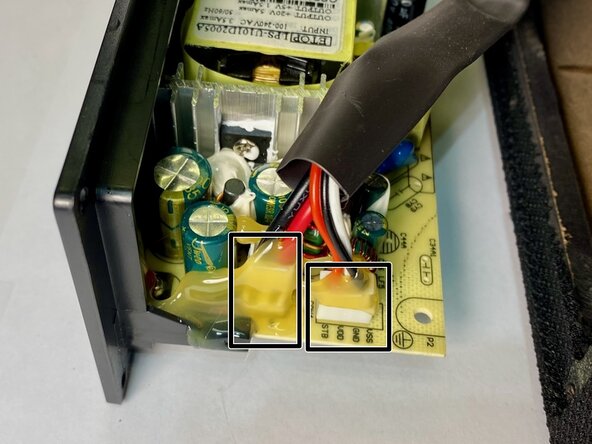
Locate the original green-bottom / yellow-top factory power supply board
-
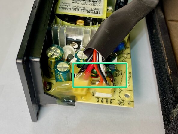
Inspect the printed text labels directly on the board to confirm your specific version layout:
-
-
-
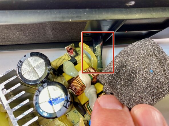
Apply isopropyl alcohol (90% or higher) to soften the factory glue holding the wire connections and the board bracket arms, then scrape it away using a plastic spudger.
-
Once the plastic bracket arms are completely clear of adhesive, gently slide the failed power supply board out of its slots. Preserve the structural integrity of these arms.
-
-
-
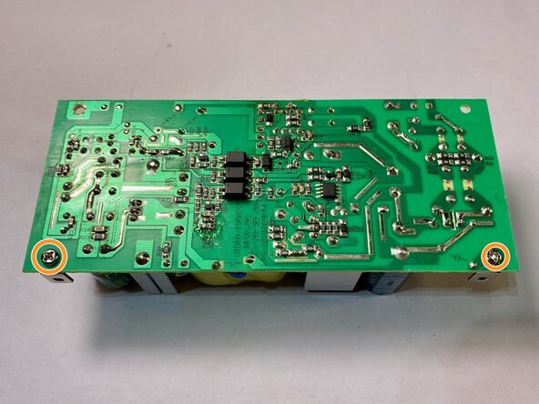
Extract the two small PH #1 Phillips screws from the `P3` and `P4` anchoring points on the lower back of the factory board.
-
Save both the metal L-brackets and screws.
-
Snip the seven wires (2 mains wires , 5 24V/5V bundled wires) connected to the failed board using wire cutters. Cut as close to the old board as possible to maximize your workable wire length. Do not discard the old board yet; keep it for troubleshooting reference.
-
-
-
-
Position the Noyito power supply over the 3D-printed adapter board. Drive the four **M3 screws** into the mounting holes to lock it down.
-
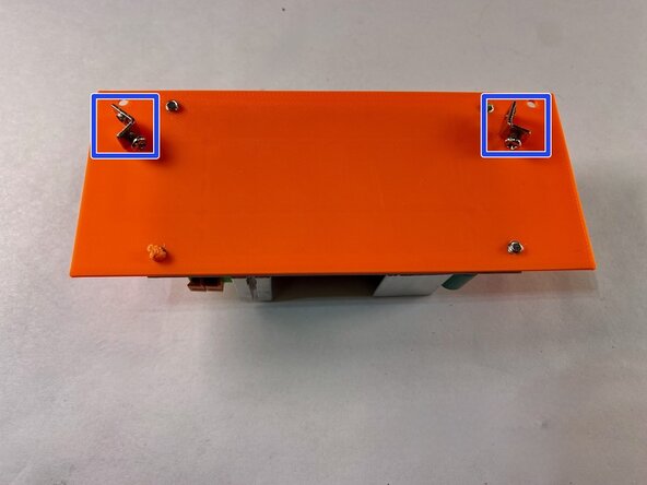
Rest the salvaged factory metal L-brackets on top of the 3D-printed adapter alignment points.
-
Insert the factory screws from the underside of the adapter board and tighten them into the brackets. The open holes on these brackets will secure the assembly back into the soundbar casing later.
-
-
-
Strip roughly 1/8-inch of insulation off the ends of all seven salvaged factory wires to expose clean copper conductors.
-
Locate the two high-voltage AC mains input wires (typically two thick red wires, or one thick red and one thick black). Insert them into the orange screw terminal block labeled 220V / AC Input and clamp or tighten them down.
-
Connect the low-voltage DC wires to the Noyito terminal block according to your verified mainboard version:
-
Connect the Thick Red Wire to DC1+ (+24V).
-
Connect the Thick Black Wire to DC1- (-24V/GND).
-
Connect your identified GND Thin Wire to DC2- (-5V/GND).
-
Twist the raw ends of your identified VDD Thin Wire and STB Thin Wire tightly together, then insert the pair directly into DC2+ (+5V).
-
-
-
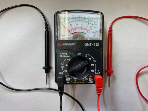
Set up your Digital Multimeter (DMM):
-
Connect the black test probe to the COM terminal.
-
Connect the red test probe to the VΩmA terminal.
-
Twist the selection dial to DC Voltage (⎓V). If using a manual-ranging meter, set the threshold range to 200V.
-
-
-
Connect an AC power cord to the input terminals and plug it into a standard wall outlet. (Green LED showing power standby.)
-
Carefully match your red meter probe to DC1+ and your black probe to DC1-. Your multimeter should display a steady reading of ~24V DC.
-
Move your red probe to DC2+ and your black probe to DC2-. Your multimeter should read a steady ~5V DC.
-
Unplug the power cord from the wall outlet and allow the onboard capacitors to completely discharge before proceeding with housing reassembly.
-
-
-
Before closing the casing, insert the two 2.5 mm hex screws from the outside of the rear cover and tighten them into the internal metal L-brackets.
-
-
-
Before testing the soundbar's external buttons, plug the AC mains cord into the wall and look directly at the green status LED on the aftermarket Noyito board:
-
LED is Completely OFF: The board is not receiving wall power. Check the 120V AC input screw terminals or the main wall outlet plug.
-
LED is Blinking or Flashing: The board's internal Short-Circuit Protection is actively tripping. Unplug the unit immediately. Check for a stray copper strand bridging the terminals on the DC output side, or reversed polarity on the thick 24V wires.
-
LED is Solid Green, but Soundbar is Dead: The power module is functional, but power is failing downstream. This points to a loose wire in the 5V line (DC2+/DC2-) or a disconnected internal wire harness.
-
-
-
If the 5V logic computer is active but the soundbar remains unresponsive or displays a flashing blue Source/Input icon, the system is stuck in a glitched software standby loop.
-
Cycle the Inputs: Press the physical Source button on top of the soundbar repeatedly to cycle through the inputs. Attempt to halt the flashing loop by forcing it onto a wired connection, such as Analog/AUX (indicated by an Orange or Green light).
-
Perform a Hardware Lock-In (10-Second Reset): While the front indicator lights are illuminated, press and hold the physical Power and Source buttons on top of the soundbar simultaneously for 10 full seconds.
-
Verify Flash: The front LEDs will flash once. This clears the glitched standby memory loop and writes a fresh boot configuration to the internal storage.
-
The Bluetooth "Jump-Start" Alternative: If the top buttons remain completely non-responsive, open your smartphone's Bluetooth settings and scan for devices. If "Cinema 600" appears, select it to connect. This digital handshake will often force a frozen motherboard to wake up, bypassing the physical buttons.
-
-
-
If your soundbar powers on and displays solid lights but outputs zero sound when an audio source is played, the 24V circuit powering the amplifiers is either lacking a physical connection or trapped in a mute state.
-
1. Check for the "Insulation Clamp" Trap: Unplug the power and inspect the DC1+ and DC1- terminal blocks. Ensure the screw clamps are crushing bare copper. It is common for these terminals to accidentally bite down on the plastic insulation jacket instead of the wire core, causing a total blockage of electrical current.
-
2. Use Remote Control: When the motherboard undergoes a forced hardware reset, it may default to a zero-volume or "Mute" state while locking out the top physical buttons. Do not use the top control panel. Aim the original Klipsch remote control at the bar and press Volume Up (+) or Mute repeatedly to force the amplifier chips to unmute.
-
3. Verify Input Channel Alignment: Ensure your audio source matches the active LED indicator color. On the Cinema 600, a Solid Orange light represents the Digital Optical channel, while a Solid Green light represents the Analog/AUX channel. If testing with an iPod or 3.5mm AUX cable, the light must be green to hear audio.
-
-
-
If the soundbar plays audio but the top control panel buttons appear completely frozen or locked up, the forced button reset has inadvertently triggered the factory Demo Mode (Retail Lock).
-
1. Ensure the soundbar is powered ON and active.
-
2. Press and hold the physical Source button and the Volume Minus (-) button on top of the soundbar simultaneously.
-
3. Keep both buttons pressed firmly for 5 to 10 seconds.
-
4. Watch the front display; the LEDs will flash once to signal that the button interface has successfully un-latched and returned to normal operation.
-
-
-
Once your bench testing confirms active logic, working buttons, and clean audio output, systematically shut down the environment to mount the final hardware safely:
-
1. Stop all audio playback and power off the soundbar using the remote control.
-
2. Unplug the 120V power cord from the wall outlet.
-
3. Wait 3 to 5 minutes for the Noyito board's green LED to completely fade out. This guarantees the high-voltage onboard capacitors are fully discharged and safe to handle.
-
4. The power supply adapter board was inserted into the internal plastic chassis slots in Step 11. Ensure no bare wires, open solder joints, or exposed circuit traces can physically contact the metallic frame of the soundbar housing.
-
5. Reinstall the rear casing and secure the 24 factory screws removed in Step 1. The 2 hex screws were reinstalled in step 11.
-
6. Take the soundbar to its permanent setup room and power it on. It will automatically broadcast its wireless signal and handshake with your subwoofer.
-
-













Reassembly instructions included in this guide.
Cancel: I did not complete this guide.
2 other people completed this guide.

2 Guide Comments
Whoever wrote this is Superman! I was so frustrated by this problem. After Klipsch refused to fix this issue, I stuffed my Cinema 600 in a closet probably a year ago. I couldn't bring myself to throw it away. I searched for a fix one more time and found this article. It is spot on. Instructions are perfectly clear. Anyone can do this. Thank you for taking the time to create this article and sharing your knowledge.
Brent: I'm so glad the instructions could help you! My Klipsch soundbar sounded fantastic for a few years - then it was completely, totally 100% dead. But with the help of lots of other people on the internet, I replaced the power module and like yours, mine lives again, up and running! -Jeff
