Introduction
This guide will instruct you on how to replace the screen in your HP ProBook 640 G3. You would typically undertake this repair if your screen is cracked, malfunctioning, or exhibiting display issues. This is an extensive replacement that is rated as Moderate in difficulty and is estimated to take about 35 minutes.
A critical safety caution before starting is to ensure the device is completely powered down and disconnected from all charging sources; it is also a good idea to make sure the laptop is not still hot before proceeding. This guide requires a significant amount of disassembly, including the battery, memory (RAM) cards, Wi-Fi card, and cooling fan, to access the screen components. The tools you will need include a Phillips #00 Screwdriver, Plastic prying tools, an Opening Pick, and Tweezers. Given the complexity, it is highly recommended to separate your screws into groups based on where they came from to aid in reassembly.
What you need
-
-
Remove the eight 6 mm-long Phillips screws securing the lower case.
-
Insert an opening pick into the seam between the lower case and chassis.
-
Slide the pick around the entire perimeter of the device until the lower case releases.
-
Remove the lower case.
 Ask FixBot
-
-
-
Use a Phillips screwdriver to loosen the seven 6 mm-long captive screws securing the battery.
-
-
-
Two clips secure each RAM module in place, one on each side. Using your fingers, spread the clips away from the RAM module.
-
Gently remove the memory from its housing by pulling it out and up.
-
-
-
-
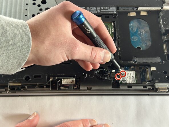
Use a Phillips screwdriver to remove the two 6 mm-long screws on the metal piece holding down the Wi-Fi card. One screw will be on top, and the other will be just next to the wires holding it in.
-
Carefully remove the little metal piece from where it was resting.
-
-
-
The only thing holding the Wi-Fi card will be two small wires. These can easily be taken off by the use of your hands or helpful tweezers.
-
Gently remove the card by pulling it out of its slot.
-
-
-
There are 22 total screws that hold down the base of the laptop. These vary between flat head Phillips and Torx head screws.
-
Remove the 2 M2.0x6
-
Remove the 8 M2.5x6 screws
-
Remove the 6 M2.0x3
-
The two screws here are M2.5x3 and M2.0x3. In the case of our device, these screws were like the battery screws, as in they did not need to be removed to continue. This could be the case with your device but if not, feel free to remove them.
-
These screws will be smaller than M2.0x3, consider sizes such as M2.0x2, M2.0x1.5, M2.0x1 and possibly smaller.
-
-
-
Locate the row of four screws along the edge of the optical drive bay (the empty slot where the DVD drive was).
-
Remove the two screws on the left (closer to the hinge/connectors). These are typically M2.0 x 3mm.
-
Remove the two screws on the right (closer to the front corner). These are typically smaller, M2.0 x 1.5mm.
-
-
-
Insert your opening pick into the seam between the top palm rest assembly (where the keyboard is) and the bottom case.
-
Slide the pick along the front and side edges to release the internal plastic clips securing the top cover.
-
Once the clips are disengaged, gently lift the keyboard compartment away to reveal the motherboard components underneath.
-
-
-
Use the Phillips head screwdriver to loosen the M2.5x1.5 screws.
-
Use the Phillips head screwdriver to loosen the M2.5x3 screw.
-
Loosen the M2.5x3.5 screws with the Phillips head screwdriver
-
Carefully detach the cooling fan and its connection from the device.
-
-
-
Locate the metal hinge brackets on the top left and top right corners of the laptop base.
-
Remove the 4 M2.5x3 screws that secure the hinges on the main chassis
-
Remove the M2.5x3.5 screws that secure the hinges
-
Remove the big M3.0x3 screw that secures the hinge
-
-
-
Before separating the screen, you must disconnect the cables connecting the display to the motherboard.
-
Carefully disconnect the display data cable (usually a flat connector) and any antenna wires located near the hinges.
-


To reassemble your device, follow the above steps in reverse order.
Take your e-waste to an R2 or e-Stewards certified recycler.
Repair didn’t go as planned? Try some basic troubleshooting or ask our Answers community for help.

Team

UMass Dartmouth, Team 1-7, Botvin Fall 2025 Member of UMass Dartmouth, Team 1-7, Botvin Fall 2025
UMASSD-BOTVIN-F25S1G7
3 Members
6 Guides authored