Introduction
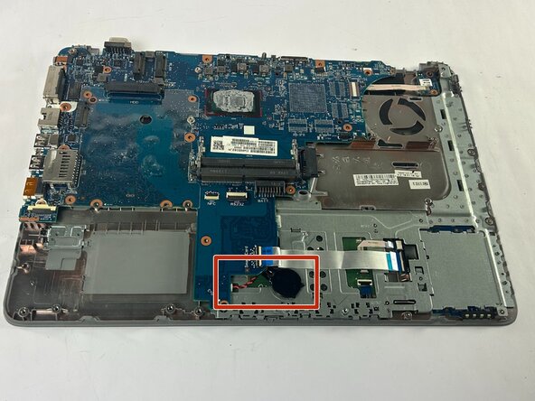
This guide covers the replacement of the small, internal motherboard battery (CMOS/RTC battery) in your HP ProBook 640 G3. This repair is typically required if your laptop is not retaining the correct date and time when it is powered off, or if you encounter BIOS configuration errors upon startup. The motherboard battery ensures that the BIOS settings are saved, even when the main battery is removed or drained.
This is a Moderate difficulty repair estimated to take 25 minutes. Due to the location of the motherboard battery, this is an extensive guide requiring the prior removal of several components, including the main battery, memory (RAM) cards, Wi-Fi card, and the cooling fan.
Before beginning, observe the crucial safety caution: ensure the device is completely powered down and disconnected from all charging sources. The tools you will need are a Phillips #00 Screwdriver, Plastic prying tools, an Opening Pick, and Tweezers. Given the number of screws involved, it is highly recommended to separate your screws into groups based on the device part they came from to aid in reassembly.
What you need
-
-
Use a Phillips screwdriver to loosen the seven 6 mm-long captive screws securing the battery.
 Ask FixBot
-
-
-
Two clips secure each RAM module in place, one on each side. Using your fingers, spread the clips away from the RAM module.
-
Gently remove the memory from its housing by pulling it out and up.
-
-
-
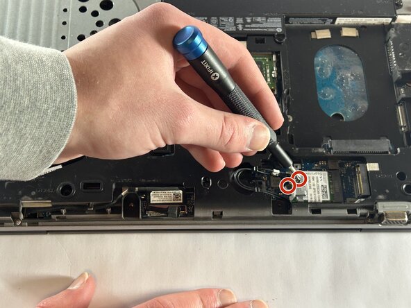
Use a Phillips screwdriver to remove the two 6 mm-long screws on the metal piece holding down the Wi-Fi card. One screw will be on top, and the other will be just next to the wires holding it in.
-
Carefully remove the little metal piece from where it was resting.
-
-
-
-
The only thing holding the Wi-Fi card will be two small wires. These can easily be taken off by the use of your hands or helpful tweezers.
-
Gently remove the card by pulling it out of its slot.
-
-
-
There are 22 total screws that hold down the base of the laptop. These vary between flat head Phillips and Torx head screws.
-
Remove the 2 M2.0x6
-
Remove the 8 M2.5x6 screws
-
Remove the 6 M2.0x3
-
The two screws here are M2.5x3 and M2.0x3. In the case of our device, these screws were like the battery screws, as in they did not need to be removed to continue. This could be the case with your device but if not, feel free to remove them.
-
These screws will be smaller than M2.0x3, consider sizes such as M2.0x2, M2.0x1.5, M2.0x1 and possibly smaller.
-
-
-
Locate the row of four screws along the edge of the optical drive bay (the empty slot where the DVD drive was).
-
Remove the two screws on the left (closer to the hinge/connectors). These are typically M2.0 x 3mm.
-
Remove the two screws on the right (closer to the front corner). These are typically smaller, M2.0 x 1.5mm.
-
-
-
Insert your opening pick into the seam between the top palm rest assembly (where the keyboard is) and the bottom case.
-
Slide the pick along the front and side edges to release the internal plastic clips securing the top cover.
-
Once the clips are disengaged, gently lift the keyboard compartment away to reveal the motherboard components underneath.
-
-
-
Use the Phillips head screwdriver to loosen the M2.5x1.5 screws.
-
Use the Phillips head screwdriver to loosen the M2.5x3 screw.
-
Loosen the M2.5x3.5 screws with the Phillips head screwdriver
-
Carefully detach the cooling fan and its connection from the device.
-
-
-
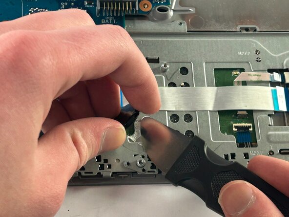
Using a prying tool, slide it under the adhesive that attaches the battery to the board.
-
Continue working the prying tool under the adhesive until the battery comes free.
-
-
-
Using your hands or a set of tweezers, carefully disconnect the battery from its motherboard port.
-








To reassemble your device, follow the above steps in reverse order.
Take your e-waste to an R2 or e-Stewards certified recycler.
Repair didn’t go as planned? Try some basic troubleshooting or ask our Answers community for help.

Team

UMass Dartmouth, Team 1-7, Botvin Fall 2025 Member of UMass Dartmouth, Team 1-7, Botvin Fall 2025
UMASSD-BOTVIN-F25S1G7
3 Members
6 Guides authored
