Introduction
This is a guide on the technique on how to terminate wires for a Garmin Avionics Install.
This is not approved material and all work done on aircraft should be done by certificated individuals per the appropriate manual.
This guide covers the use of a twisted pair wire but the technique is applicable to any shielded wire.
-
-
-
DMC crimpers with appropriate turret
-
Wire strippers
-
Flush cuts
-
Razor
-
Fine tip sharpie, or label printer for wires
-
Heat gun
 Ask FixBot
-
-
-
Wire
-
Shield braid
-
Heat shrink (2 pieces), at least one piece white
-
Environmental splice
-
Pins
-
-
-
Interior wires- where the signal is passed through
-
Outer layer of insulation
-
Shielding- a braid inside the wire over the interior wires. This protects the signal from interference or interfering with other signals. The shielding is terminated to a ground
-
-
-
-
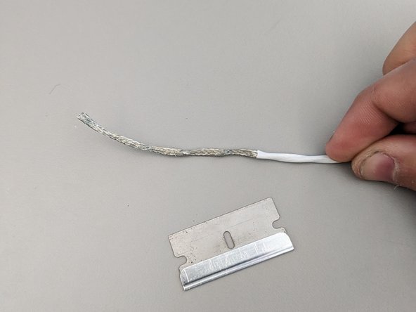
Remove shielding to expose wires
-
Option 1: unbraid shield and the cut away from wire
-
Option 2: carefully cut shield away without nicking the interior wires
-
-
-
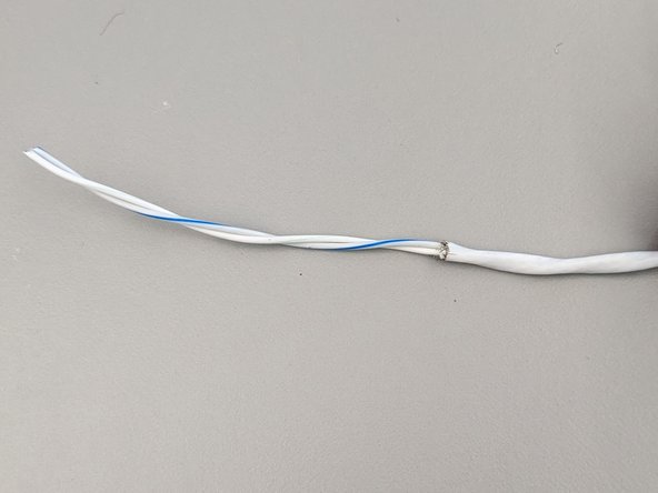
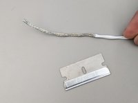
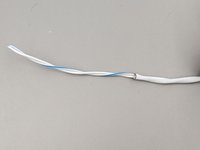
Cut a 0.25" long section from outer layer of the wire about 2.5" from the end of the wire.
-
This accomplished with a razor. A new razor will cut more easily through the insulation but can also cut through the shielding. A dull razor is harder to cut with but also more forgiving to mistakes.
-
If the shielding is cut through and the interior wires nicked there is a high potential for a short to ground and that section of wire must be cut off and the wire must be restarted.
-
-
-
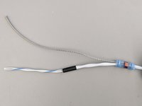
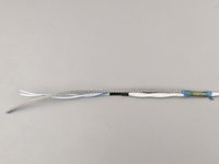
Insert the environmental splice over the cut shielding block and insert the shield braid into it. The solder ring must go over both the exposed shield and the braid.
-
Insert a piece of heat shrink over the end of the wire where the shield and outer insulation is cut. This will protect the end of the wire
-
Heat the splice and heat-shrink with a heat gun. Ensure the solder flows in the splice soldering the braid to the shield.
-
-
-
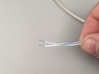
Strip wires appropriate length - detailed in next step
-
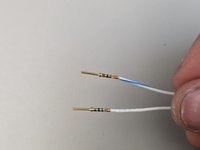
Crimp terminals to wire
-
-
-
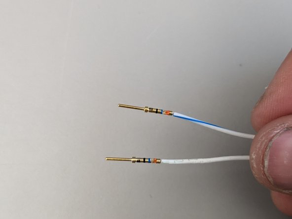
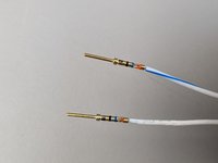
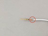
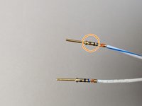
The wire strip length should by just barely longer than the barrel (where the wire goes) of the crimped contact
-
First picture shows a correct termination
-
Second picture shows to long of strip on wire
-
To make sure the wire is stripped long enough the conductor strands should be visible in the witness hole circled in the third picture
-
-
-
Add heat-shrink with wire number added to it to identify wire after install
-
-
-
Push pins into connector, the should lock into place and need a special tool for removal
-
-
-
Crimp ring terminal to shield braid
-
Install ring terminal to designated grounding location. Often the connector back-shell.
-
This step is done last after all wires for a connector are installed and back-shell is assembled on connector. Sometimes a separate ground lug needs to be installed onto the back-shell.
-
-










Cancel: I did not complete this guide.
2 other people completed this guide.

