
Epson PPC650 Screen Replacement

Last updated on Jul 1, 2025
Views: 956
View statistics:
- Past 24 Hours:
- 1
- Past 7 Days:
- 12
- Past 30 Days:
- 91
- All Time:
- 956
Comments: 0
No one has left comments on this guide. Will you be first?
Go to guide commentsCompleted: 0 1
No one has marked this guide "completed." Will you be the first?
1 person has marked this guide "completed." It's you — great job!
Favorites: 0 1
No one has favorited (and subscribed to) this guide. Will you be the first?
1 person has favorited (and subscribed to) this guide — and that's you!
Needs Better Images
Better photos will improve this guide. Help out by taking, editing, or uploading new ones!
Needs More Images
A few more images would make this guide's procedures crystal clear.
Introduction
Go to step 1 ↓If your Epson PPC650’s screen is cracked, unresponsive, or displaying distorted images, this guide will walk you through replacing the screen to restore full functionality.
Before beginning, check for any loose connections or software issues that might be causing display problems. If the screen remains unresponsive or physically damaged, replacement is necessary.
This repair requires careful handling of delicate components. If the screen is shattered, use protective gloves to avoid injury. Additionally, be sure to power off the device and disconnect it from any external power sources before starting the repair.
What you need
Tools
-
-
Spudger4.9
-
-


-
-
-
Locate the silver power button. Gently slide the button to the middle section labeled "off" to shut down the camera.
-
Remove the batteries from the battery compartment located on the underside of the camera.
-
Remove the SD card from the compartment located on the flat, left side of the camera.
 Ask FixBot
-
-
-
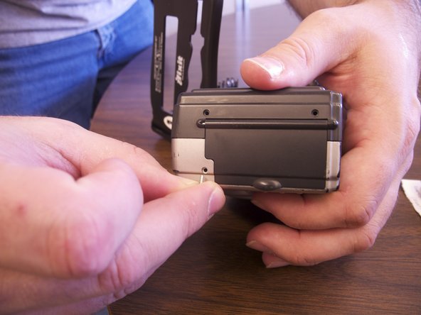
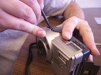
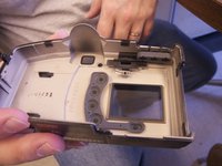
Separate the front and the back pieces of the camera's plastic casing using a spudger.
-
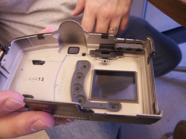
When separating the small silver siding, the indicator for the view/off/playback may fall out.
-
The plastic viewing window located on the top of the camera may also become lose and fall out.
-
-
-
-
-
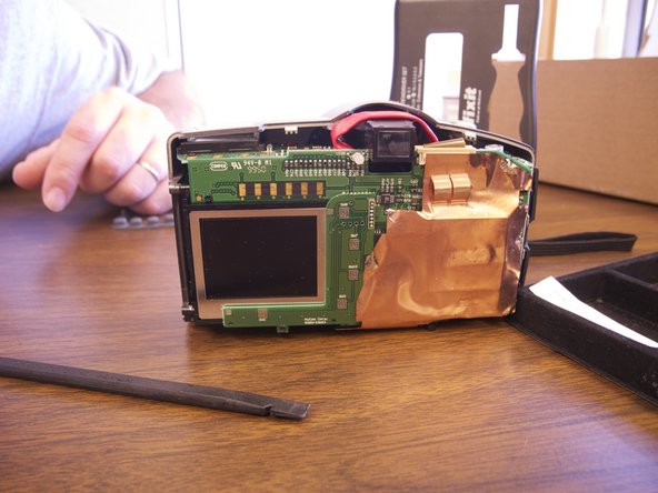
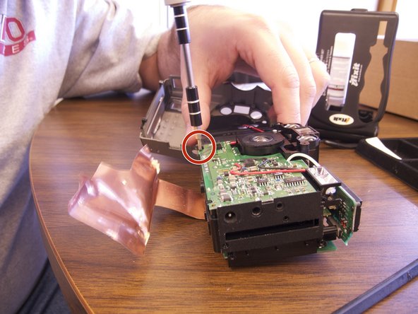
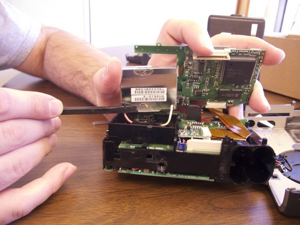
Remove the copper sheet from the front and back paneling.
-
Use the spudger to unsolder the copper paneling.
-
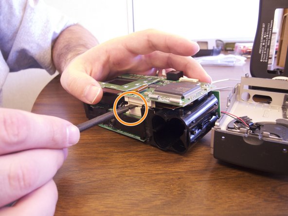
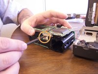
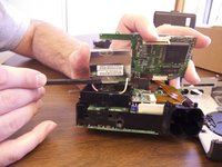
Use the spudger to separate the back circuit board from the camera.
-
-
-
-
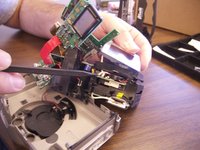
Exert minimal force to pull the screen loose from the camera.
-
Remove the pink and white wiring from the internal paneling. These wires are soldered in.
-
Remove the orange data hookup cable that feeds into the back circuit board.
-
-
-
Once all wires have been detached and the old screen has been removed place the new screen into the camera.
-
Insert data hookup into the back of the camera and into the new screen.
-
Re-solder the new pink and white wire onto the internal circuit board.
-
-






To reassemble your device, follow these instructions in reverse order.

Team

Ohio State, Team 1-5, Buehl Spring 2013 Member of Ohio State, Team 1-5, Buehl Spring 2013
OSU-BUEHL-S13S1G5
4 Members
36 Guides authored
