
Disassembling a Monroe LA-160 calculator

robertcbaruch and 4 other contributors
Last updated on Jul 26, 2024
Views: 3.8K
View statistics:
- Past 24 Hours:
- 5
- Past 7 Days:
- 16
- Past 30 Days:
- 111
- All Time:
- 3,761
Comments: 2
2 guide comments.
Go to guide commentsCompleted: 4 5
4 people have marked this guide "completed." Will you be next?
5 people have marked this guide "completed." Including you — great job!
Favorites: 1 2
1 person has favorited (and subscribed to) this guide. Will you be next?
2 people have favorited (and subscribed to) this guide — including you!
Community-Contributed Guide
An awesome member of our community made this guide. It was not created by iFixit staff.
Introduction
Go to step 1 ↓Ever been at a garage/boot sale, flea market, or junk shop and seen a weird thing that looks like a cash register and a typewriter mated? These are electromechanical calculators which our dads and granddads used in the office because electronic calculators were far off in the future.
There are many of these now on eBay, but many of them are less than functional. The last time they were used was probably in the 1960s, and all the grease has probably congealed and picked up dust and twigs and things. Also, decades of being moved around and not being serviced means that parts go out of alignment or get broken by the well-meaning and the inquisitive.
Worse, the manuals and repair guides for these machines are either rare or nonexistent. My dad tells me that a man came round the office every month to maintain the calculators. It's likely that any repair information stayed inside the company.
And so, this disassembly guide will help you take this calculator to pieces so that the pieces can be cleaned, repaired, or replaced. And hopefully you'll learn a bit about the mechanisms that make these machines go.
The specific calculator we're going to be taking apart is the Monroe LA-160. The LA-160 is of the L series of Monroe calculators introduced in 1928, with the A meaning Automatic, that is, with an electric motor attached. This model has a 16-digit accumulator and an 8-digit counter, and can multiply and divide (manually) by successive addition and subtraction.
What you need
Tools
-
×2

-
-
-
Prepare your workspace. Cover it with clean white paper or a white mat board. Light the area more than you think you'll need, and preferably from multiple directions.
-
Ready a cardboard box and lots of press-to-close bags to store the parts you pull off. Keep associated parts in their own bag, label each bag, and don't skimp on the number of bags!
 Ask FixBot
-
-
-
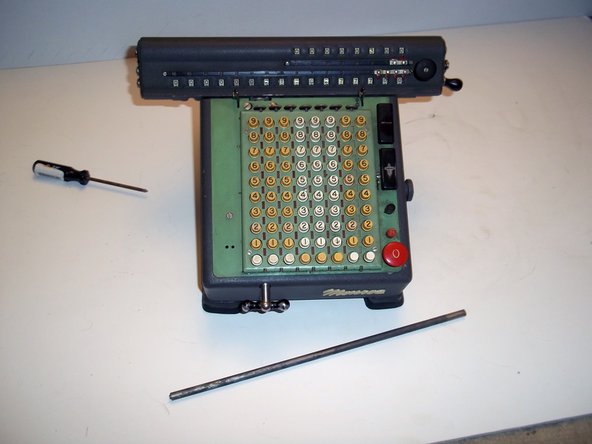
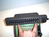
Let's first remove the carriage, which is the top part with all the number wheels on them.
-
Position the calculator so that its keyboard faces you. This orientation defines the left and right sides of the calculator.
-
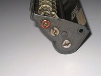
Insert a 1/8" flathead screwdriver into each of the indicated two screwheads on the right and left sides of the carriage, simultaneously.
-
Unscrew the left side screw.
-
-
-
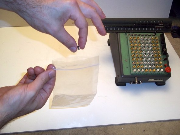
Remove the left side screw.
-
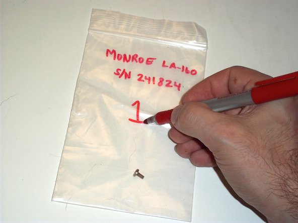
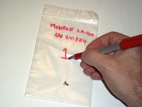
Put it in a bag!
-
You should label each bag with the model number and serial number.
-
You can find the serial number by turning the calculator upside down and peering into the slot cut into the bottom, which gives you the model number and serial number.
-
Label the bag 1 so that you know where in the sequence this part was pulled off.
-
-
-
Put the bag in a box labeled with the model and serial number.
-
Pat yourself on the back. You are now officially organized.
-
-
-
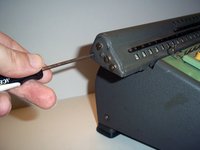
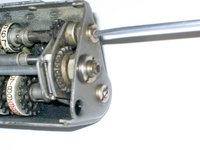
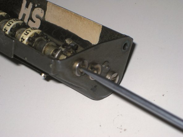
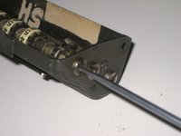
Get something pointy, like a small screwdriver, and push it into the hole on the left side of the carriage that was revealed by the screw being removed.
-
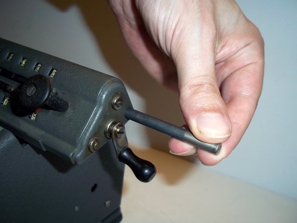
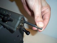
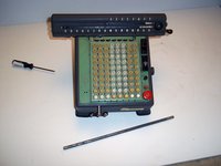
This will push out the carriage shaft from the right side. Grab it and pull it out all the way.
-
Put the carriage shaft in your box of parts.
-
-
-
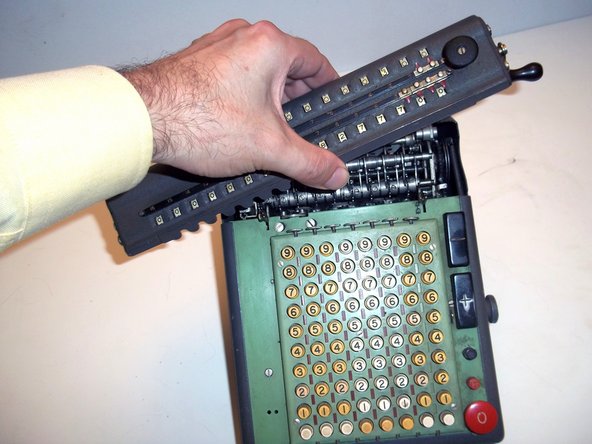
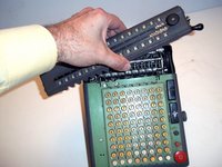
Pull back on the two carriage latches.
-
With the other hand, lift the carriage up and away.
-
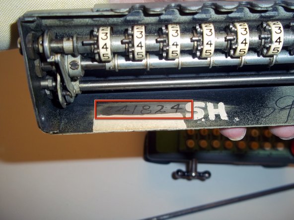
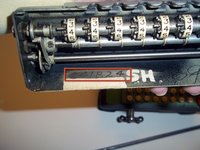
On the underside of the carriage is inscribed the serial number of the machine, in case you couldn't read it from the slot in the underside.
-
Mine is serial number 241824. Also, apparently Stapler Guy was really possessive of this calculator.
-
-
-
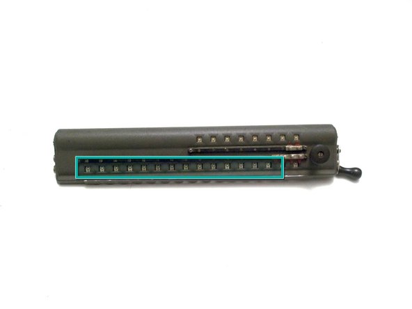
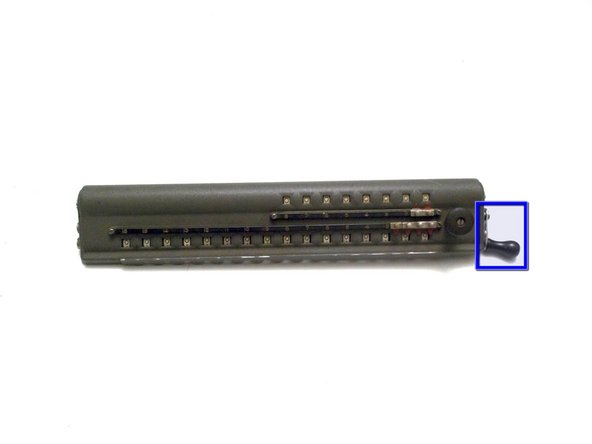
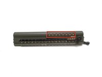
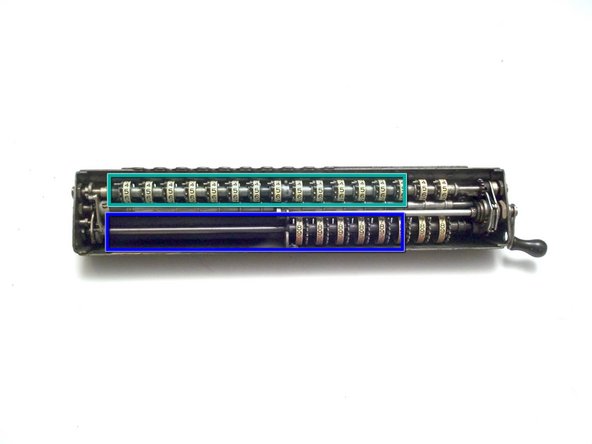
Upper Dials. Consists of eight individual dials with black and red digits. Shows the multiplier in multiplication, and the result of division.
-
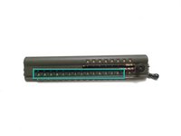
Lower Dials. Consists of sixteen individual dials, showing the result of addition and multiplication, the remainder in subtraction, and the dividend in division.
-
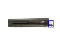
Dials Clear-out Crank. Rotate forwards one turn, stopping at bottom, to clear out upper dials. Backwards for lower dials.
-
-
-
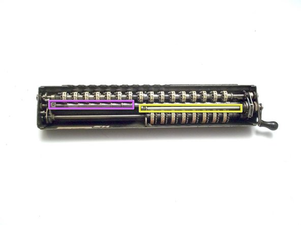
Clutch mechanism. Drives either the lower shaft or upper shaft, but not both.
-
Lower Dials shaft and wheels.
-
Upper Dials shaft and wheels.
-
Zeroing shaft.
-
Carriage lifting shaft, only active when zeroing the Lower Dials.
-
-
-
Nelson White's U.S. patent "Zero-setting mechanism", filed in 1920, describes how this amazing thing works.
-
The clutch rotates one gear forwards when the crank is turned forwards, and it rotates another gear backwards when the crank is turned backwards.
-
One gear turns the upper shaft, the other gear turns the lower shaft. Little arms on the clutch lock the shafts into place when they are not turning.
-
On the left side of the carriage, cams on the upper and lower dials move a lever on the central zeroing shaft. Fingers on the zeroing shaft as a result move into place so that when the upper or lower shaft is rotated, the wheels stop when they display zero.
-
The zeroing mechanism rarely completely fails. It is useful to rotate the crank while observing all the different parts to gain an understanding of each part's function.
-
-
-
Turn the carriage to the right side.
-
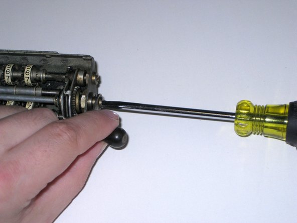
Holding on to the crank, remove this screw.
-
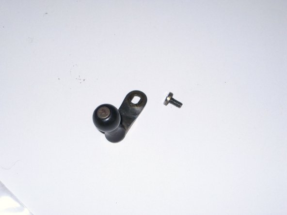
Put the crank and screw in bag #1.
-
-
-
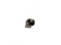
Remove this set screw.
-
Set screw: 5-44 x 1/8"
-
Put the set screw in bag #1.
-
-
-
Turn the carriage to the left side.
-
Remove this set screw.
-
Set screw: 5-44 x 1/8"
-
Place the set screw in bag #1.
-
The set screws are used to align the shaft along its axis.
-
-
-
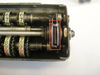
This spring on the right side of the carriage needs to be removed.
-
Pull the arm on the right upwards to get better access to the spring.
-
-
-
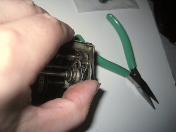
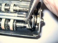
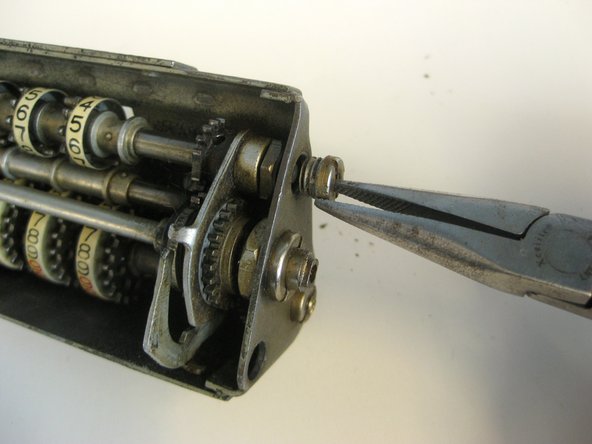
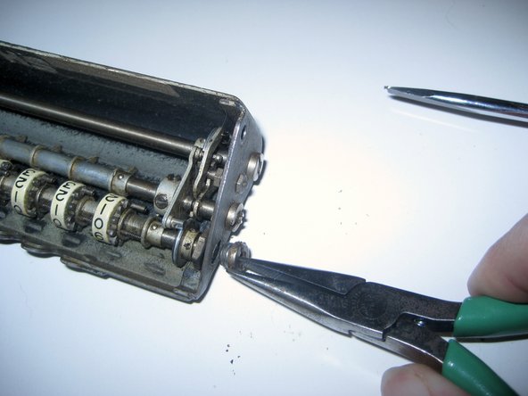
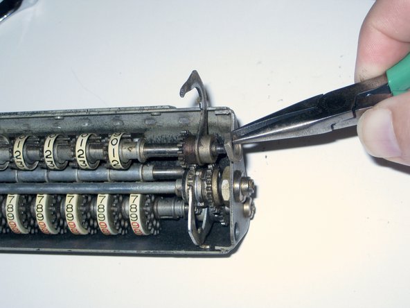
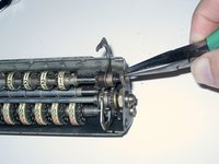
With the arm raised, use needlenose pliers to pull the spring off the arms.
-
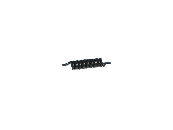
Spring: Expansion, 0.31" compressed x 0.11", wire 0.014"
-
Place the spring in bag #1.
-
-
-
Spread the arms out.
-
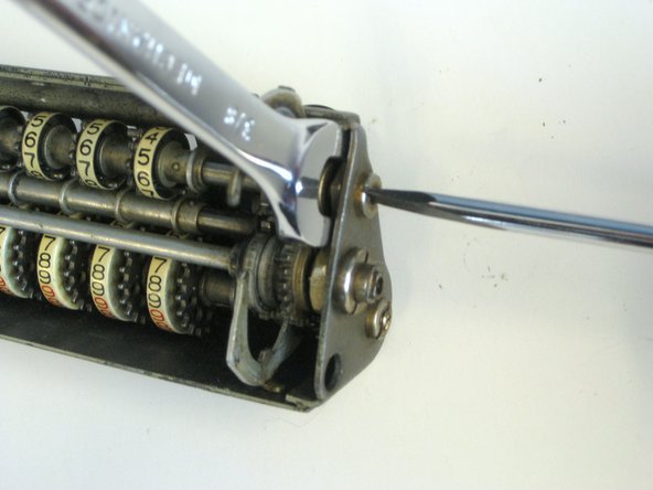
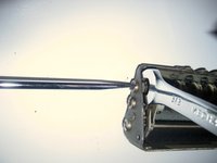
Use a 3/8" wrench to hold the nut, and unscrew the bushing.
-
Remove the bushing, and put it in bag #1.
-
The nut stays in for now.
-
-
-
-
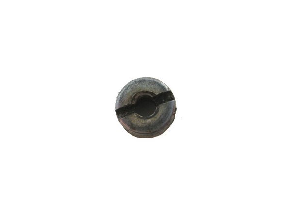
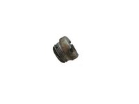
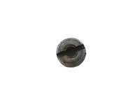
A close-up of the bushing.
-
It is hollow and threaded on the outside, 1/4-32 x 1/8", and the head is threaded on the inside for the set screw.
-
Its head is 0.296" x 3/16"
-
-
-
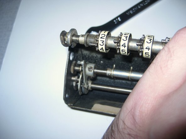
On the right side, lift up the Lower Dials shaft by the arm.
-
You can now get to the nut. Remove it and put it in bag #1.
-
-
-
Still lifting on the right side of the shaft, turn the shaft so that the cam on the left side engages the pin.
-
Now lift up on the left side of the shaft to free it.
-
The left side nut may fall off, or not. If it tries to escape, make sure you see where it went.
-
-
-
Remove the nut from the left side of the shaft, or the floor, or wherever it ended up, and place it in bag #1.
-
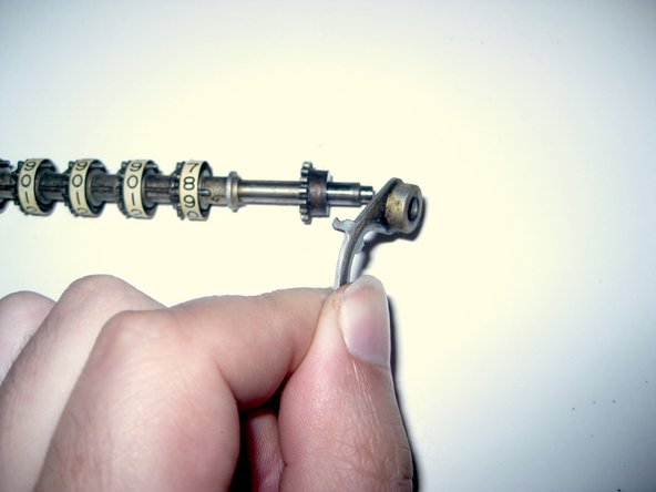
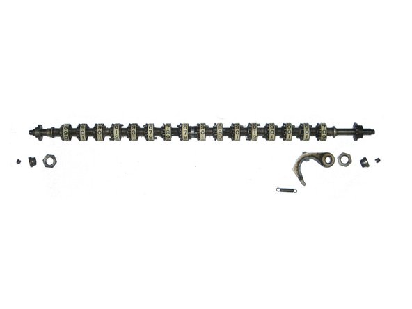
Remove the Lower Dials shaft arm from the right side of the shaft, and place it in bag #1.
-
-
-
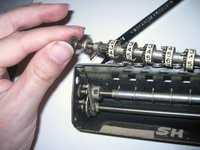
The parts of the Lower Dials are fixed to the shaft using tapered pins.
-
During installation, the part is placed on the shaft, held in place, and then a hole is drilled through the part and the shaft using a taper pin drill bit.
-
Next, a taper pin is inserted into the hole until it stops, then it is pressed in with an arbor press. The pin is then cut or ground off.
-
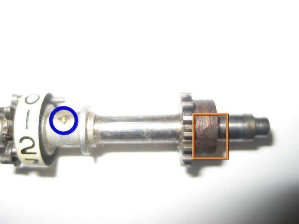
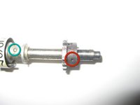
Indicated is a hole in the Lower Dials driver gear for its taper pin.
-
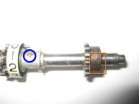
In this dial spacer, the taper pin is clearly visible.
-
Rotating the shaft to the other side, we can see the over-enthusiastic application of a grinding head applied to the other end of the taper pin on the driver gear.
-
Meanwhile, the taper pin is again clearly visible on the dial spacer.
-
-
-
Removal of taper pins requires an arbor press and pin punches, and preferably a pin punch holder.
-
For this disassembly, you will need 1.1 mm or 1.0 mm pin punches, and you will need a lot of them, maybe ten or twenty, since they will often break.
-
Before you use a pin punch, cut it down to 1/4" or so using a Dremel or some other cut-off tool.
-
-























Wowzers!
Cancel: I did not complete this guide.
4 other people completed this guide.

