This translation was generated by a machine and has not been reviewed by a person yet. Speak this language? Review it.

Dell Latitude 5591 PC Build

Modixia and one other contributor
Last updated on Sep 2, 2026
Views: 298
View statistics:
- Past 24 Hours:
- 3
- Past 7 Days:
- 13
- Past 30 Days:
- 67
- All Time:
- 298
Comments: 0
No one has left comments on this guide. Will you be first?
Go to guide commentsCompleted: 1 2
1 person has marked this guide "completed." Will you be next?
2 people have marked this guide "completed." Including you — great job!
Favorites: 0 1
No one has favorited (and subscribed to) this guide. Will you be the first?
1 person has favorited (and subscribed to) this guide — and that's you!
Needs More Images
A few more images would make this guide's procedures crystal clear.
Community-Contributed Guide
An awesome member of our community made this guide. It was not created by iFixit staff.
Introduction
Go to step 1 ↓This guide explains how to assemble a Restart PC using a Dell Latitude 5591 motherboard: wiring the power button and LED, adding a USB expansion card and a SATA expansion card, and then securing the assembly into the housing.
What you need
Parts
Tools


-
-
-
Change the BIOS battery and secure it using double-sided tape.
-
Add a RAM stick.
-
Add a Wi-Fi card.
-
Boot the board with the Windows drive already installed (it has a sticky note).
 Ask FixBot
-
-
-
Remove the black sheath.
-
Connect the port to the motherboard.
-
-
-
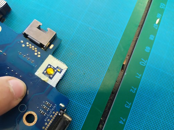
Remove the black plastics from both sides of the button board.
-
Remove the rubber that is around the button and the LED.
-
Remove the yellow adhesive from the rubber.
-
-
-
Cut the twisted wires.
-
35cm for the LED.
-
42cm for the button.
-
Strip and tin the 4 wire ends.
-
-
-
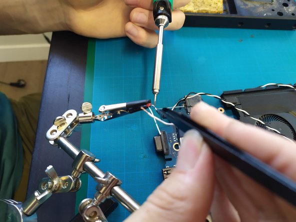
Solder the black and white wires for the button and front LED (see photo).
-
Test the button solder joints using the multimeter in "continuity tester" mode.
-
Connect the alligator clips to the black and white wires.
-
Press the original button. If the multimeter beeps, it's good, and you can move on to the next step.
-
-
-
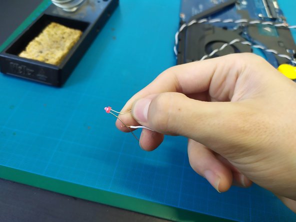
Plug in the PC and try to start it to test the LED polarity; the LED positive (the longer leg) goes to the white wire.
-
Add the heat shrink tubing.
-
Solder the LED.
-
Heat the heat shrink tubing with the heat gun.
-
-
-
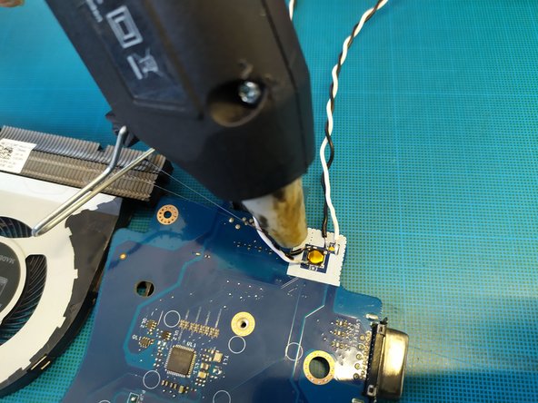
Use a hot glue gun to apply glue over the solder joints to reinforce them.
-
Perform a final check to ensure everything is working properly.
-
-
-
Drive the 2 short M3 Torx screws.
-
Drive the 3 M2 Phillips screws.
-
-
-
Deburr the holes for the USB extension using a Phillips screwdriver.
-
Insert the USB-A extension into its slot, with the long cable from the blue box in the bottom beige shelf.
-
Use 2 Phillips m3 screws to secure the USB extension.
-
-
-
Drive 4 short M3x6 Torx screws WITHOUT TIGHTENING.
-
-
-
Flip the assembly over.
-
Remove one screw.
-
Insert a drop of threadlocker.
-
Reinstall the screw, still WITHOUT TIGHTENING.
-
Repeat the green dots for the 4 M3 screws.
-
Tighten the 4 screws one by one.
-
-
-
Route the extension under the motherboard.
-
Connect the extension to the original connector.
-
Hide the connector under the motherboard.
-
-
-
Route the USB cables under the motherboard.
-
Connect the various cables to the corresponding ports using the adapters.
-
90° horizontal adapter.
-
USB-C 90° horizontal adapter.
-
USB-A 3.0 180° adapter.
-
-
-
Add a drop of threadlocker.
-
Screw in one short M3 Torx screw per block WITHOUT TIGHTENING.
-
Once all blocks are installed, tighten the screws one by one.
-
1x hub block.
-
1x USB-C power block.
-
1x DELL air vent block.
-
1x HDMI block.
-
1x RJ45 block.
-
-
-
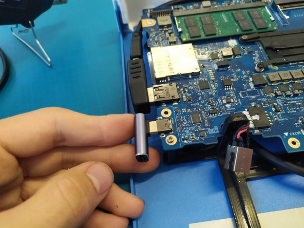
Connect the magnetic-to-USB-C adapter.
-
Then, connect the USB-C expansion card.
-
-
-
Add a cable tie to the HDMI cables.
-
Cut off the excess with flush cutters.
-
Hide the "knot" under the cable.
-
-
-
-
Connect the SSD.
-
Secure the three 3x6 mm Phillips screws.
-
-
-
In our batch of PCs, we didn't have any speakers, which is why they are missing from the photos.
-
Secure the speakers using screws. No idea which ones... good luck ;).
-
Connect the speakers and hide the cable (see photo).
-
-
-
Add a drop of threadlocker.
-
Secure the air duct with 2 M2 Phillips screws.
-
Repeat the green points for the dust cover.
-
-
-
Glue the antennas in place using a glue gun.
-
Connect the antennas.
-
Tuck the cables under the motherboard.
-
-
-
Cut a grounding block.
-
Stick the block down.
-
-
-
Install the upper plate.
-
Secure with 4 black M3 Phillips FHC screws (skip this step if parts are missing).
-
-










Cancel: I did not complete this guide.
One other person completed this guide.

