Free Shipping on Domestic Orders $75+

Connecting Cables to the Motherboard

What you need

  1. Connecting Cables to the Motherboard, Connecting Cables to the Motherboard: step 1, image 1 of 2 Connecting Cables to the Motherboard, Connecting Cables to the Motherboard: step 1, image 2 of 2
    • Red- Optional ATX Connector

    • Orange- CPU Fan 1

    • Yellow- CPU Fan 2

    • Green- Main ATX Connectors

    • Light Blue- GPU

    • Blue- Panel Connectors

    • Pink- USB Connectors

    • Black- HD Audio

    Ask FixBot

    Add Comment

  2. Connecting Cables to the Motherboard, Optional ATX Connector: step 2, image 1 of 2 Connecting Cables to the Motherboard, Optional ATX Connector: step 2, image 2 of 2
    • Connect the two separate six-pin segments to six pins each on the 12-pin PCIE port.

    Ask FixBot

    Add Comment

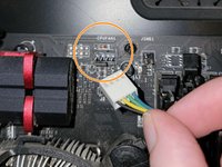
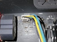
  3. Connecting Cables to the Motherboard, CPU Fan 1: step 3, image 1 of 2 Connecting Cables to the Motherboard, CPU Fan 1: step 3, image 2 of 2
    • Connect the four pin segment to the four pin PCEI connector labeled "CPUFAN1."

    Ask FixBot

    Add Comment

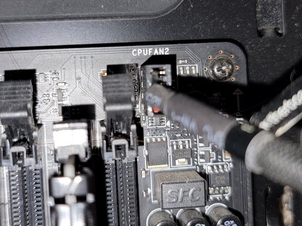
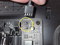
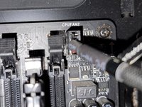
  4. Connecting Cables to the Motherboard, CPU Fan 2: step 4, image 1 of 2 Connecting Cables to the Motherboard, CPU Fan 2: step 4, image 2 of 2
    • Connect the four pin segment to the four pin PCIE port labeled "CPUFAN2."

    Ask FixBot

    Add Comment

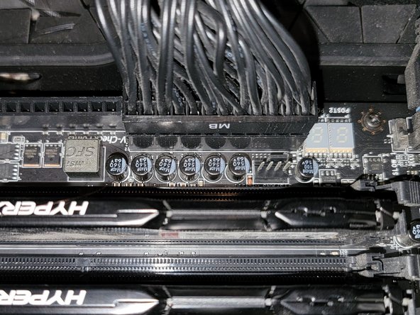
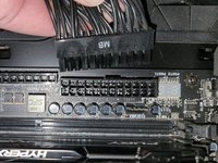
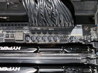
  5. Connecting Cables to the Motherboard, Main ATX Connector: step 5, image 1 of 2 Connecting Cables to the Motherboard, Main ATX Connector: step 5, image 2 of 2
    • Connect the 24 pin segment to the 24 pin PCIE port.

    Ask FixBot

    Add Comment

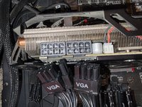
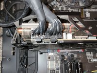
  6. Connecting Cables to the Motherboard, GPU: step 6, image 1 of 2 Connecting Cables to the Motherboard, GPU: step 6, image 2 of 2
    • Connect both of the separate eight pin segments to each of the eight pin PCIE ports on the graphics card.

    Ask FixBot

    Add Comment

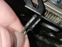
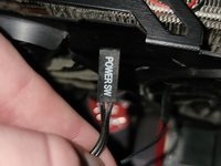
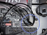
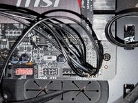
  7. Connecting Cables to the Motherboard, Panel Connectors (Part 1): step 7, image 1 of 3 Connecting Cables to the Motherboard, Panel Connectors (Part 1): step 7, image 2 of 3 Connecting Cables to the Motherboard, Panel Connectors (Part 1): step 7, image 3 of 3
    • This PCIE port consists of eight pins, two rows of four.

    • Connect the "Power LED+" pin to the pin at the top right corner.

    • Connect the "Power LED-" segment to the pin next to the "Power LED+" segment in the top row.

    • Connect the "Power SW" segment to the two pins on the left side of the top row of pins.

    Ask FixBot

    Add Comment

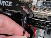
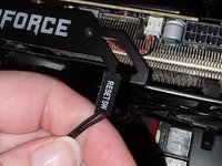
  8. Connecting Cables to the Motherboard, Panel Connectors (Part 2): step 8, image 1 of 3 Connecting Cables to the Motherboard, Panel Connectors (Part 2): step 8, image 2 of 3 Connecting Cables to the Motherboard, Panel Connectors (Part 2): step 8, image 3 of 3
    • Connect the "HDD LED" segment to the two pins on the right side of the bottom row of pins.

    • Connect the "Reset SW" segment to the two pins on the left side of the bottom row of pins.

    Ask FixBot

    Add Comment

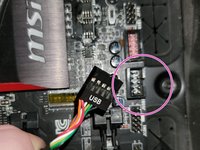
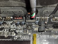
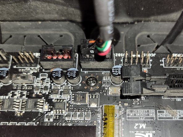
  9. Connecting Cables to the Motherboard, USB Connector: step 9, image 1 of 2 Connecting Cables to the Motherboard, USB Connector: step 9, image 2 of 2
    • Connect the nine pin segment to the nine pin PCIE port.

    Ask FixBot

    Add Comment

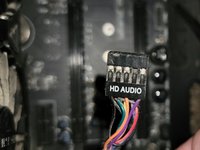
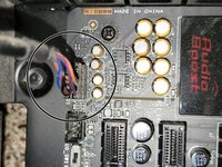
  10. Connecting Cables to the Motherboard, HD Audio: step 10, image 1 of 2 Connecting Cables to the Motherboard, HD Audio: step 10, image 2 of 2
    • Connect the nine pin segment to the nine pin PCIE port.

    Ask FixBot

    Add Comment

Conclusion

To disconnect the cable ties, follow these directions in reverse order.

Cancel: I did not complete this guide.

2 other people completed this guide.

Grace Parsekian

Member since: 12/05/23

250 Reputation

1 Guide authored

1 Guide Comment

Rest comment brancher un processeur. Merci comme-me.

Kader Lahcene - Reply Share
Add Comment

View Statistics:

Past 24 Hours: 42

Past 7 Days: 293

Past 30 Days: 1,215

All Time: 28,779