Introduction
This guide shows you how to replace the shutter dial assembly. The shutter dial assembly includes the shutter dial and the shutter button.
Note that the Phillips #000 screwdriver is marked as an optional tool as you can always use the JIS #000 screwdriver in its place (JIS screwdrivers won't damage Phillips head screws).
What you need
-
-
Before beginning, remove the battery and SD card from the camera.
-
Remove the eyepiece.
-
Using a pair of tweezers, unclip each side of the eyepiece from the bottom while providing light pressure upwards on the eyepiece with your thumb.
-
Remove the battery door.
-
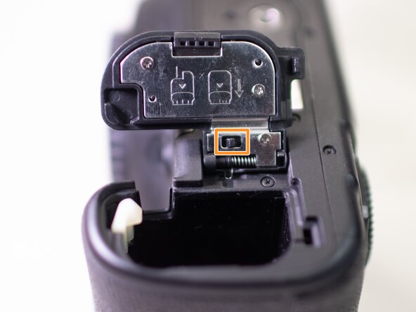
Open the battery door and disengage the hinge spring.
-
While holding the spring back, pull off the battery door.
 Ask FixBot
-
-
-
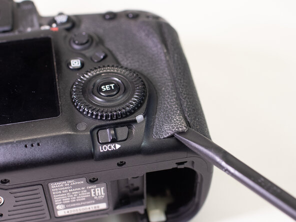
Using a plastic spudger tool, peel off the rubber grip on the left side of the camera.
-
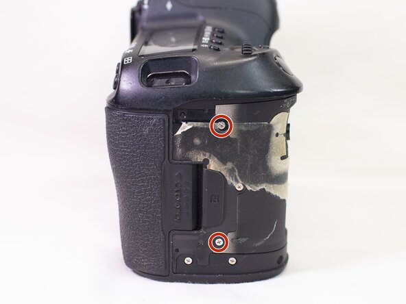
On the Left side of the camera, underneath where the rubber grip was, remove the following screws:
-
Two M1.7x5.0mm Phillips #000 screws.
-
One M1.7x5.0mm Phillips #000 screw.
-
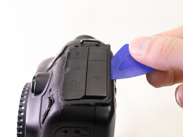
Pry off the plastic interface cover.
-
-
-
With a plastic spudger tool, peel off the rubber grip on the backside of the camera.
-
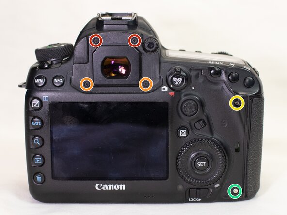
On the backside of the camera, remove the following screws:
-
Two M1.7x4.5mm JIS #000 screws.
-
Two M1.7x6.0mm JIS #000 screws.
-
One M1.7x9.0 JIS #000 screw.
-
One M1.7x4.5mm Phillips #000 screw.
-
-
-
On the bottom of the camera, remove the following screws:
-
Three M1.7x2.5mm JIS #000 screws.
-
Slightly lift up the back cover from the camera, using a plastic spudger or opening tool as needed.
-
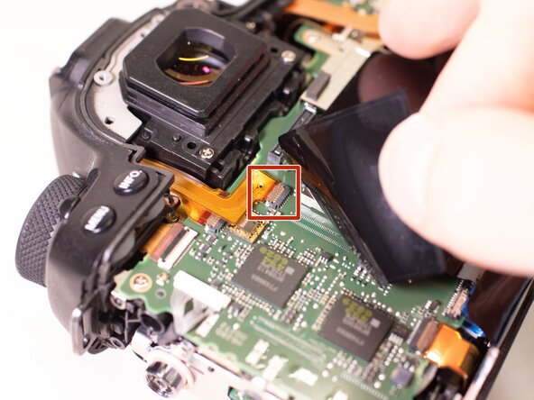
Carefully pry up the ribbon cable attaching the screen to the main PCB board using a plastic spudger.
-
With the cable disconnected, you can finish lifting off the back cover from the camera.
-
-
-
-
Using a plastic spudger tool, peel off the right rubber grip.
-
On the front of the camera, remove the following screws:
-
One M1.7x5.0mm Phillips #000 screw.
-
Two M1.7x2.8mm Phillips #000 screws.
-
Two M1.7x5.5mm JIS #000 screws.
-
Two M1.7x7.0mm Phillips #000 screws.
-
-
-
On the right side of the camera, remove the following screws:
-
Two M1.7x4.0mm Phillips #000 screws.
-
On the bottom of the camera, remove the following screw:
-
One M1.7x5.5mm JIS #000 screw.
-
-
-
With a plastic spudger tool, carefully remove the two cables that connects the front cover to the main PCB board.
-
Pull the front cover off the camera body, using a plastic spudger or opening tools as needed.
-
-
-
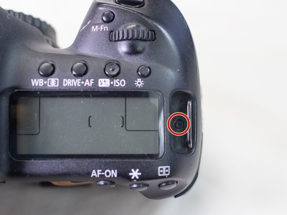
Remove the following Screws from the top cover:
-
One M1.7x7.0mm JIS #000 screw.
-
One M1.7x4.5mm Phillips #000 screw.
-
Remove the diopter using a JIS #000 screwdriver.
-
-
-
Hold up the plastic cover on the main PCB board.
-
Disconnect the ribbon cable underneath this plastic cover.
-
Using a plastic spudger tool, carefully pry up the brown plastic locking tab.
-
Once the locking tab is lifted up, you can carefully pull out the ribbon cable.
-
Repeat the steps above to remove the second ribbon cable.
-
-
-
On the right side of the PCB board, remove the last ribbon cable that connect the top cover to the main PCB board.
-
Gently pry up on the connector using a plastic spudger tool.
-
With all the ribbon cables disconnected, carefully lift up and remove the top cover from the rest of the camera.
-
-
-
Remove the following screws on the shutter dial assembly:
-
Three M1.7x4.5mm JIS #000 screws.
-
Two M1.7x6.0mm JIS #000 screws.
-
Disconnect the ribbon cable connecting the shutter dial assembly to the top cover.
-
Gently pull up and remove the shutter dial assembly from the top cover.
-













To reassemble your device, follow these instructions in reverse order.
Attached Documents

