Introduction
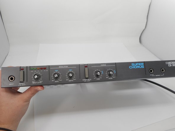
This guide provides step-by-step instructions to replace the dials on the Boss CE-300 Super Chorus, a vintage analog effects processor known for its rich chorus sounds. The dials, which control parameters like chorus level and tone, may wear out over time, resulting in inconsistent adjustments or complete failure. Replacing them restores functionality and ensures precise control.
The process involves disassembling the device, removing the faceplate, and carefully de-soldering the old dials from the circuit board before soldering new ones in place. Essential tools include a Phillips #2 screwdriver, 11mm and 14mm wrenches, a soldering iron, and a desoldering pump or braid for safe removal of solder joints.
This task requires basic soldering skills and attention to detail to avoid damage to the circuit board. Follow each step carefully, and ensure the device is powered off and unplugged before beginning to ensure safety and success.
What you need
-
-
Use a Phillips #2 screwdriver to remove the 3 14.8 mm screws located on the left side of the CE-300.
-
Repeat the previous bullet on the right side.
 Ask FixBot
-
-
-
On the back of the CE-300, remove the two 7.5 mm screws with a Phillips #2 screwdriver.
-
-
-
On the left side, remove the one 10 mm screws with a Phillips #2 screwdriver.
-
Repeat the previous bullet on the right side.
-
-
-
Remove the following screws with a Phillips #2 screwdriver:
-
Two 7.5 mm
-
Two 10 mm
-
-
-
-
Remove the single 5.7 mm screw on the left side of the face plate.
-
Repeat the previous step on the right side of the face plate.
-
-
-
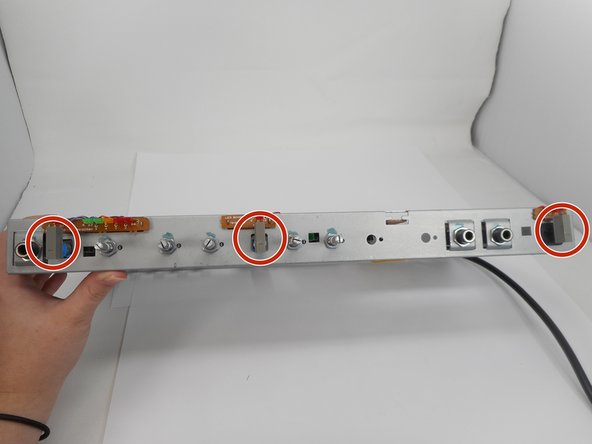
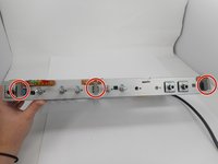
From the inside of the unit, pinch the 3 clips holding the faceplate in
-
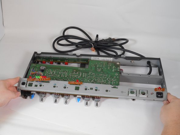
Push the clips in and the face plate will slide off.
-
-
-
Use a Phillips #2 screwdriver to remove the single 7.8 mm screw on the left side of the bracket.
-
Repeat the previous bullet on the right side of the bracket.
-
-
-
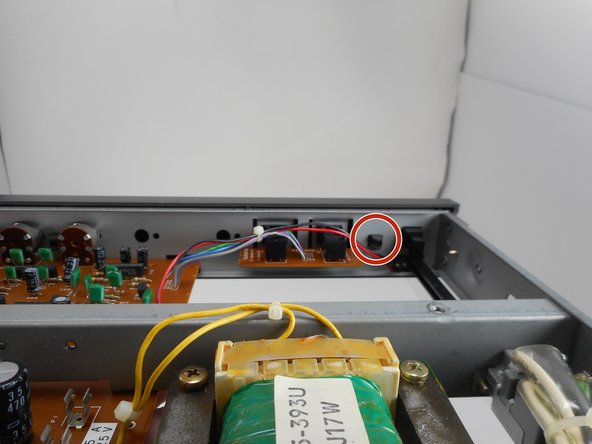
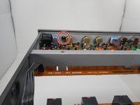
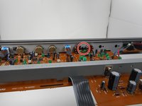
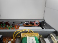
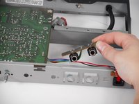
Remove the two audio jacks that are to the side.
-
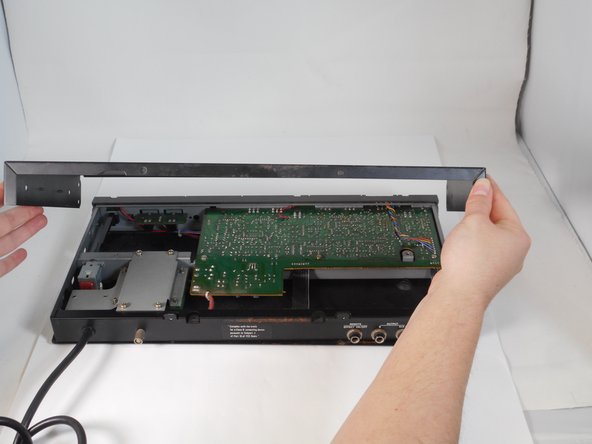
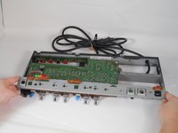
Carefully remove the face bracket by sliding it forward until it clears all dials, then lift up.
-
-
-
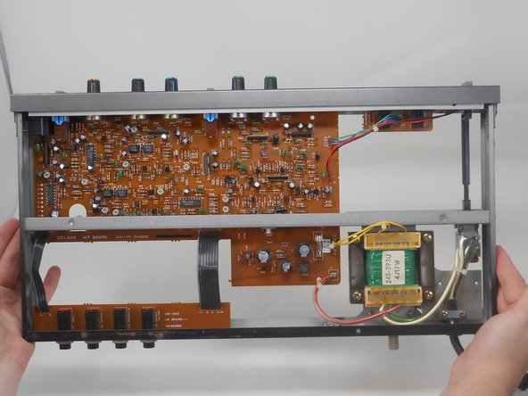
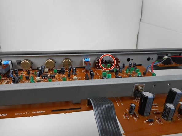
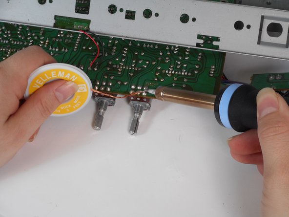
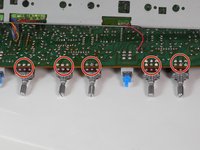
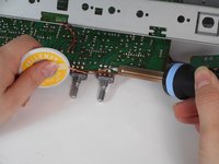
Desolder the marked joints from the "top" of the board.
-
Remove the dials.
-












To reassemble your device, follow the above steps in reverse order.
Take your e-waste to an R2 or e-Stewards certified recycler.
Repair didn’t go as planned? Try some basic troubleshooting or ask our Answers community for help.

Team

University of Memphis, Team 1-2, Sneed Fall 2024 Member of University of Memphis, Team 1-2, Sneed Fall 2024
UM-SNEED-F24S1G2
4 Members
9 Guides authored
