This translation was generated by a machine and has not been reviewed by a person yet. Speak this language? Review it.

Bosch 70A Alternator Disassembly and Inspection

Silke and 3 other contributors
Last updated on Sep 2, 2026
Views: 1.9K
View statistics:
- Past 24 Hours:
- 10
- Past 7 Days:
- 65
- Past 30 Days:
- 291
- All Time:
- 1,893
Comments: 0
No one has left comments on this guide. Will you be first?
Go to guide commentsCompleted: 0 1
No one has marked this guide "completed." Will you be the first?
1 person has marked this guide "completed." It's you — great job!
Favorites: 0 1
No one has favorited (and subscribed to) this guide. Will you be the first?
1 person has favorited (and subscribed to) this guide — and that's you!
Community-Contributed Guide
An awesome member of our community made this guide. It was not created by iFixit staff.
Introduction
Go to step 1 ↓When your Bosch 70A alternator has around 300,000 km on it and still puts out less than 14 V with a new voltage regulator, it may be time to overhaul it. To do that, you first need to disassemble the alternator and check the typical wear parts. These include the regulator, commutator segments, bearings, diodes, and stator winding. Use the opportunity to clean the heavily soiled generator with brake cleaner or something similar.
What you need

-
-
-
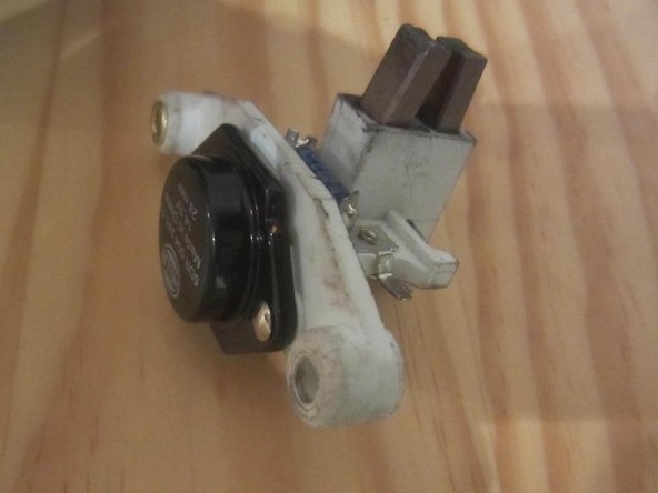
Remove the regulator: two screws (slotted in the original)
-
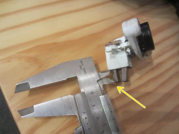
The carbon brushes should still protrude by at least 5 mm, otherwise replace the carbon brushes or the entire regulator. Here they are 12 mm.
 Ask FixBot
-
-
-
On older alternators, the screws may be rusted solid. Spray generously with rust remover or penetrating oil and allow to soak in for a while if necessary.
-
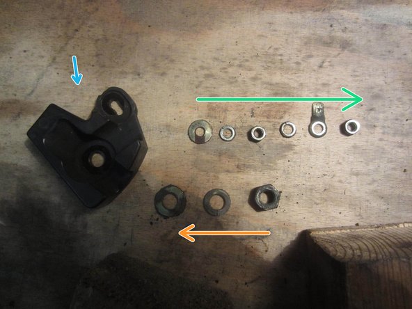
Unscrew the nuts and washers (if present) on the two/four pull arms.
-
Unscrew the nuts and washers on the positive contact bolt (13 mm).
-
Unscrew the nuts, washers, and contact tongue from the control line (7 mm).
-
Unscrew the nuts, washers, and contact tab from the control line (7 mm).
-
-
-
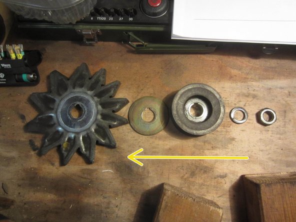
Unscrew the belt pulley: hold it in place with an old belt and unscrew it with a wrench or ratchet. (22 mm)
-
Remove the nut and all washers as well as the fan blade, noting the order.
-
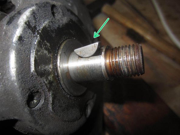
Remove the crescent key.
-
-
-
Mark the alternator housing for later reassembly.
-
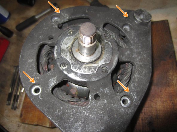
If the four tie rods (screws) are of different lengths, note or mark where each one belongs
-
Unscrew the four screws (PH2).
-
Pull out the front housing part with the stator, using a plastic hammer to help if necessary.
-
-
-
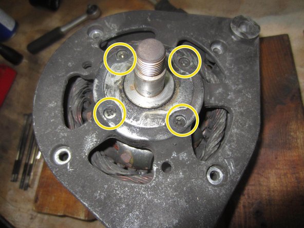
Remove the four countersunk screws
-
Pull the rotor out of the bearing shield (housing).
-
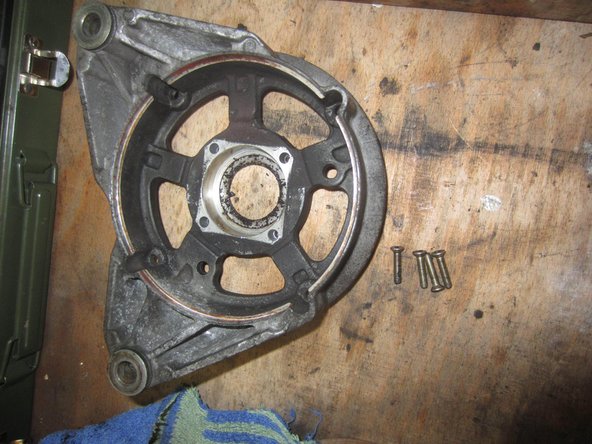
Bearing shield and screws
-
-
-
Check: between the commutator segments 2.8 ohms +/- 10%, no contact with the housing?
-
Even if the resistance is correct, the contacts are so worn that the commutator ring must be replaced.
-
-
-
This step is also necessary to replace the commutator ring
-
Remove the two bearings from the rotor shaft; a good bearing puller is helpful.
-
-
-
-
In the rear housing, remove the two screws that connect the diode plate to the housing
-
Pull the diode set and stator winding out of the housing
-
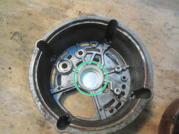
Do not lose the plastic bushing (or sliding ring).
-
-
-
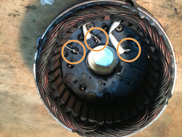
Desolder the three stator cables.
-
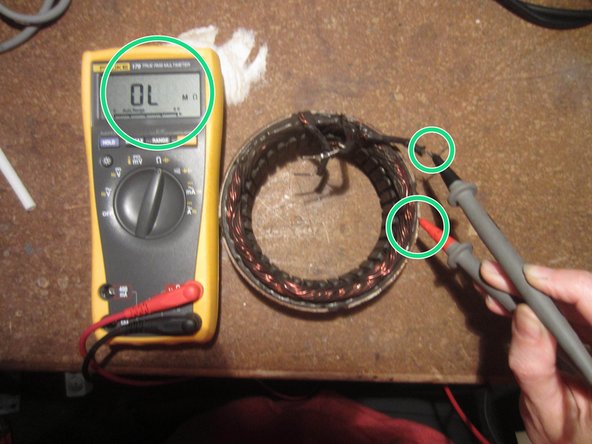
Check the stator windings for short circuits to ground. Target: infinite resistance
-
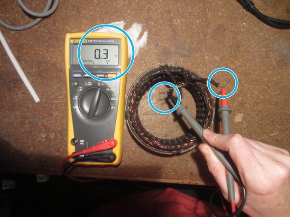
Check continuity of the stator windings (the displayed 0.3 ohms) are inaccurate but continuity is present
-
-
-
Test the rectifier diodes in forward and reverse bias. An intact diode conducts only in one direction.
-
If a diode conducts in both directions or not at all, replace the rectifier as a unit.
-
-













Follow the steps in reverse order to reassemble your device.
Special thanks to these translators:
100%


These translators are helping us fix the world! Want to contribute?
Start translating ›