
Aux Plug Repair

Bayden Yazalina and 3 other contributors
Last updated on Aug 20, 2026
Views: 1.2K
View statistics:
- Past 24 Hours:
- 5
- Past 7 Days:
- 58
- Past 30 Days:
- 201
- All Time:
- 1,164
Comments: 0
No one has left comments on this guide. Will you be first?
Go to guide commentsCompleted: 0 1
No one has marked this guide "completed." Will you be the first?
1 person has marked this guide "completed." It's you — great job!
Favorites: 0 1
No one has favorited (and subscribed to) this guide. Will you be the first?
1 person has favorited (and subscribed to) this guide — and that's you!
Community-Contributed Guide
An awesome member of our community made this guide. It was not created by iFixit staff.
Introduction
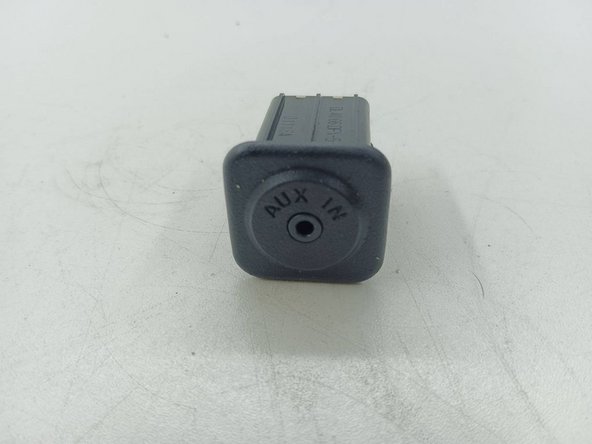
Go to step 1 ↓This auxiliary input requires detection of a plug in order to be selected on the radio. These pins wear out, resulting in the inability to select the auxiliary input regardless of if a device is connected or not. Repairing this involves removing the auxiliary input and soldering the detection pins together.
-
-
-
The auxiliary input is in a plastic housing that needs to be pried out, and it does not come out easily. A small pry tool or flathead screwdriver will suffice, but it will require some time to free the clips on the sides of the housing.
-
There are small clips on either two sides of the housing, a few millimeters from the edge on either side. A metal pry tool was the most effective, as slightly bending the plastic around the housing seems necessary.
 Ask FixBot
-
-
-
Once the plastic housing is free, the connection can be removed by pushing down the central tab on the plug.
-
To remove the circuit board, loosen the externally-visible clips with a small pry tool and pull it out of the housing.
-
-
-
-
The circuit board will have (from top to bottom) two Phillips screws, six small solder points, one solder point, two solder points, four solder points, and two solder points. The important row is the one with six solder points.
-
With the Phillips screws at the top, the pins to solder together are the two leftmost pins. Be careful to ensure that no other pins are bridged, as damage could occur to your stereo.
-
Be sure to test your solder job before reassembly by plugging the circuit board back into the car and testing it.
-
-


To reassemble your device, follow these instructions in reverse order.

