Free Shipping on Domestic Orders $75+

Autosampler Battery Enclosure Assembly (For Old & New Versions)

Views: 653

View statistics:

Past 24 Hours:
2
Past 7 Days:
16
Past 30 Days:
63
All Time:
653
Comments: 2

2 comments on steps.

Completed: 1

1 person has marked this guide "completed." Will you be next?

Favorites: 0

No one has favorited (and subscribed to) this guide. Will you be the first?

Time Required: 2 hours
Difficulty: Moderate
Community-Contributed Guide

An awesome member of our community made this guide. It was not created by iFixit staff.

Autosampler Battery Enclosure Assembly (For Old & New Versions)
    1. Autosampler Battery Enclosure Assembly (For Old & New Versions), Drill the holes into the enclosure.: step 1, image 1 of 3 Autosampler Battery Enclosure Assembly (For Old & New Versions), Drill the holes into the enclosure.: step 1, image 2 of 3 Autosampler Battery Enclosure Assembly (For Old & New Versions), Drill the holes into the enclosure.: step 1, image 3 of 3
      • 1. Drill a hole in the top right corner 16.5 mm from the top and 30.3 mm from the side using a 13/16 inch drill bit.

      • 2. Drill two holes in the side 30 mm from the short sides and 27 mm from the long side using a 1/2 inch drill bit.

      • 3. Screw in two waterproof cable gland connectors to the side holes.

      • Put in a button in the rocker switch in the other hole.

      Ask FixBot

      Add Comment

    2. Autosampler Battery Enclosure Assembly (For Old & New Versions), Prepare the battery wires.: step 2, image 1 of 2 Autosampler Battery Enclosure Assembly (For Old & New Versions), Prepare the battery wires.: step 2, image 2 of 2
      • 4. Cut the purple wire and the inline fuse holder wire 10 inches long.

      • 5. Attach a 10A, 12VDC fuse.

      Ask FixBot

      Add Comment

    3. Autosampler Battery Enclosure Assembly (For Old & New Versions), Prepare the wires for the batteries.: step 3, image 1 of 3 Autosampler Battery Enclosure Assembly (For Old & New Versions), Prepare the wires for the batteries.: step 3, image 2 of 3 Autosampler Battery Enclosure Assembly (For Old & New Versions), Prepare the wires for the batteries.: step 3, image 3 of 3
      • 6. Strip both wires about 1/2 inch

      • 7. using the 16 gauge slot of the wire stripper

      • 8. Get 3 pink and 3 blue fully insulated heat-shrink quick-disconnect terminals.

      Ask FixBot

      Add Comment

    4. Autosampler Battery Enclosure Assembly (For Old & New Versions), Attach heat-shrinking terminals.: step 4, image 1 of 3 Autosampler Battery Enclosure Assembly (For Old & New Versions), Attach heat-shrinking terminals.: step 4, image 2 of 3 Autosampler Battery Enclosure Assembly (For Old & New Versions), Attach heat-shrinking terminals.: step 4, image 3 of 3
      • 9. Crimp the fully insulated heat-shrink quick-disconnect terminal onto the end of the wire.

      • 10. Use the heat shrink gun to heat shrink the ends of the crimps.

      • 11. Repeat for both ends of both wires.

      Ask FixBot

      Add Comment

    5. Autosampler Battery Enclosure Assembly (For Old & New Versions), Prepare the battery connector wire.: step 5, image 1 of 2 Autosampler Battery Enclosure Assembly (For Old & New Versions), Prepare the battery connector wire.: step 5, image 2 of 2
      • 12. Cut two feet of red and black 16G wire (grey insulated wire) and then strip 2 inches off of the grey insulation.

      • 13. Strip 1/2 inch of both the black and red wires.

      Ask FixBot

      Add Comment

    6. Autosampler Battery Enclosure Assembly (For Old & New Versions), Prepare the battery connector wire.: step 6, image 1 of 3 Autosampler Battery Enclosure Assembly (For Old & New Versions), Prepare the battery connector wire.: step 6, image 2 of 3 Autosampler Battery Enclosure Assembly (For Old & New Versions), Prepare the battery connector wire.: step 6, image 3 of 3
      • 14. Place two metal contacts on both the red and black wires.

      • You should see copper wire through the little pin hole. If not, strip more insulation.

      • 15. Crimp the contacts into place.

      • 16. Thread the contacts into the Amphenol connector.

      Ask FixBot

      Add Comment

    7. Autosampler Battery Enclosure Assembly (For Old & New Versions), Prepare the battery connector wire.: step 7, image 1 of 3 Autosampler Battery Enclosure Assembly (For Old & New Versions), Prepare the battery connector wire.: step 7, image 2 of 3 Autosampler Battery Enclosure Assembly (For Old & New Versions), Prepare the battery connector wire.: step 7, image 3 of 3
      • 17. Attach the green wedge to the connector.

      • 18. Cut 1.5 inches of 2:1 0.25" diameter heat shrink tubing.

      • 19. Use the heat shrink gun to shrink the heat shrink tubing.

      Ask FixBot

      Add Comment

    8. Autosampler Battery Enclosure Assembly (For Old & New Versions), final battery connector.: step 8, image 1 of 1
      • 20. This is what the final battery connector looks like.

      Ask FixBot

      Add Comment

    9. Autosampler Battery Enclosure Assembly (For Old & New Versions), Creating a 2-pin amphenol connector.: step 9, image 1 of 3 Autosampler Battery Enclosure Assembly (For Old & New Versions), Creating a 2-pin amphenol connector.: step 9, image 2 of 3 Autosampler Battery Enclosure Assembly (For Old & New Versions), Creating a 2-pin amphenol connector.: step 9, image 3 of 3
      • 21. Cut 30 inches of red and black 16G wire (grey insulated wire). Strip 2 inches of the grey rubber coating from both ends.

      • 22. Strip 0.5 inches from both the red and black wires from both ends.

      • 23. Obtain a 2-pin amphenol connector.

      Ask FixBot

      Add Comment

    10. Autosampler Battery Enclosure Assembly (For Old & New Versions), Creating a 2-pin amphenol connector.: step 10, image 1 of 3 Autosampler Battery Enclosure Assembly (For Old & New Versions), Creating a 2-pin amphenol connector.: step 10, image 2 of 3 Autosampler Battery Enclosure Assembly (For Old & New Versions), Creating a 2-pin amphenol connector.: step 10, image 3 of 3
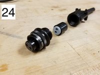
      • 24. Disconnect the 2-pin amphenol connector into its individual parts.

      • 25. Loosen the screws on the amphenol connector. Thread the stripped wire through the end of the amphenol connector and through the middle piece of the amphenol connector.

      • The black GND wire should be in the “A” port and the red PWR wire should be in the “B” port.

      • 26. Solder the wires to the other end of the amphenol connector.

      Ask FixBot

      Add Comment

    11. Autosampler Battery Enclosure Assembly (For Old & New Versions), Creating a 2-pin amphenol connector.: step 11, image 1 of 3 Autosampler Battery Enclosure Assembly (For Old & New Versions), Creating a 2-pin amphenol connector.: step 11, image 2 of 3 Autosampler Battery Enclosure Assembly (For Old & New Versions), Creating a 2-pin amphenol connector.: step 11, image 3 of 3
      • 27. Obtain a Flux Remover Pen, 99 % Isopropyl Alcohol, and a Q-Tip.

      • 28. Use the pen to remove the flux from the soldered pins.

      • 29. Dip the q-tip in the alcohol. Use the q-tip to remove the flux remover.

      Ask FixBot

      Add Comment

    12. Autosampler Battery Enclosure Assembly (For Old & New Versions), Creating a 2-pin amphenol connector.: step 12, image 1 of 3 Autosampler Battery Enclosure Assembly (For Old & New Versions), Creating a 2-pin amphenol connector.: step 12, image 2 of 3 Autosampler Battery Enclosure Assembly (For Old & New Versions), Creating a 2-pin amphenol connector.: step 12, image 3 of 3
      • 30. Screw the amphenol pieces back together. Then tighten the external screws.

      • 31. This is what a final 2-pin amphenol connector looks like.

      • 32. Thread the 2-pin amphenol autosampler wire through the top hole and the battery connector wire through the bottom hole of the enclosure box. Leave about a foot of each on the outside of the box. Tighten the glands.

      Ask FixBot

      Add Comment

      • Once 2 pin and battery wires constructed and threaded into box, strip opposite ends and add heat-shrinking quick disconnect terminals.

      Ask FixBot

      Add Comment

    13. Autosampler Battery Enclosure Assembly (For Old & New Versions), Connecting wires to the rocker switch.: step 14, image 1 of 3 Autosampler Battery Enclosure Assembly (For Old & New Versions), Connecting wires to the rocker switch.: step 14, image 2 of 3 Autosampler Battery Enclosure Assembly (For Old & New Versions), Connecting wires to the rocker switch.: step 14, image 3 of 3
      • 33. This is what the wires look like threaded through the glands in the box.

      • 34. Connect the battery wire to the first two prongs of the rocker switch.

      • 35. Connect the 2-pin amphenol autosampler wire to the last two prongs of the rocker switch.

      Ask FixBot

      Add Comment

    14. Autosampler Battery Enclosure Assembly (For Old & New Versions), Connecting the battery in the enclosure.: step 15, image 1 of 3 Autosampler Battery Enclosure Assembly (For Old & New Versions), Connecting the battery in the enclosure.: step 15, image 2 of 3 Autosampler Battery Enclosure Assembly (For Old & New Versions), Connecting the battery in the enclosure.: step 15, image 3 of 3
      • 36. Connect the purple wire and fuse wire to the middle two prongs of the rocker switch.

      • 37. Connect the other side of the purple wire and fuse wire to a 12 volt battery.

      • 38. A light goes on if the fuse is blown!

      Ask FixBot

      Add Comment

    15. Autosampler Battery Enclosure Assembly (For Old & New Versions), Completing the enclosure.: step 16, image 1 of 3 Autosampler Battery Enclosure Assembly (For Old & New Versions), Completing the enclosure.: step 16, image 2 of 3 Autosampler Battery Enclosure Assembly (For Old & New Versions), Completing the enclosure.: step 16, image 3 of 3
      • 39. Place the 12V battery and all the wires into the enclosure.

      • 40. Screw the lid onto the enclosure.

      • 41. This is what the completed battery enclosure looks like.

      Ask FixBot

      Add Comment

    16. Autosampler Battery Enclosure Assembly (For Old & New Versions), Label the switch: step 17, image 1 of 1
      • Label the switch with the label maker.

      • <-- Manual Mode

      • --> Node Trigger Mode

      Ask FixBot

      Add Comment

Finish Line

Cancel: I did not complete this guide.

One other person completed this guide.

Brooke Mason

Member since: 05/29/19

2,958 Reputation

17 Guides authored

Team

Open-Storm Member of Open-Storm

Community

16 Members

288 Guides authored

0 Guide Comments

Add Comment

View Statistics:

Past 24 Hours: 2

Past 7 Days: 16

Past 30 Days: 63

All Time: 653