Free Shipping on Domestic Orders $75+

Astak Mole Camera Head Replacement

Views: 1.1K

View statistics:

Past 24 Hours:
2
Past 7 Days:
12
Past 30 Days:
94
All Time:
1,071
Comments: 2

2 comments on steps.

Completed: 0

No one has marked this guide "completed." Will you be the first?

Favorites: 0

No one has favorited (and subscribed to) this guide. Will you be the first?

Time Required: 10 minutes
Difficulty: Difficult
Incorrect Tools

Help make this guide better by using the correct tools in images and/or text.

Slice and Dice

The steps in this guide should be split up and made into a series of prerequisite guides.

Astak Mole Camera Head Replacement

Introduction

Go to step 1 ↓

In order for you to replace the camera head, you will have to separate the base and the camera head by disconnecting some wires that lead from the head to the motherboard.

What you need

Tools

  • Spudger
    4.9
  • Phillips #1 Screwdriver
    5
    1. Astak Mole Camera Head Replacement, Lower Case: step 1, image 1 of 1
      • Remove the four bottom tabs in order to access the bottom screws.

      Ask FixBot

      Add Comment

    2. Astak Mole Camera Head Replacement: step 2, image 1 of 1
      • Remove all four 14 mm Phillips #1 screws.

      Ask FixBot

      Add Comment

    3. Astak Mole Camera Head Replacement: step 3, image 1 of 1
      • Remove the SD card.

      Ask FixBot

      Add Comment

    4. Astak Mole Camera Head Replacement: step 4, image 1 of 1
      • Pry up the motherboard on the four points using a spudger.

      • The regular black nylon spudger should be used whenever possible, especially around sensitive internal components.

      Ask FixBot

      Add Comment

    5. Astak Mole Camera Head Replacement: step 5, image 1 of 1
      • Gently pull back the motherboard to expose many of the component's wired connections.

      Ask FixBot

      Add Comment

    1. Astak Mole Camera Head Replacement, Camera Head: step 6, image 1 of 1
      • Unscrew the three screws connecting the base to the camera head with the PH1 size Phillips head bit.

      • Screw measurements: Length=7.0mm.

      • The third screw can be exposed by rotating the camera head.

      • Do not force the camera head farther than it will allow you.

      Ask FixBot

      Add Comment

    2. Astak Mole Camera Head Replacement: step 7, image 1 of 1
      • Unscrew indicated Phillips head screws using the PH1 Phillips head bit to free wires.

      • Screw measurements: Length=3.5mm

      Ask FixBot

      Add Comment

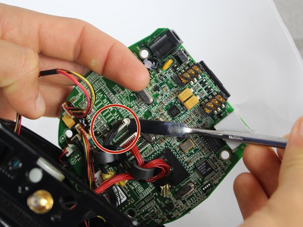
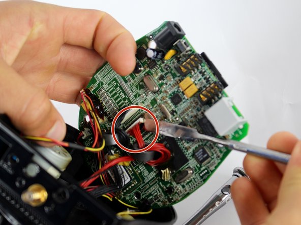
    3. Astak Mole Camera Head Replacement: step 8, image 1 of 3 Astak Mole Camera Head Replacement: step 8, image 2 of 3 Astak Mole Camera Head Replacement: step 8, image 3 of 3
      • Separate the three indicated outputs from the motherboard with metal spudger.

      • There is electrical adhesive on the output. This can be easily separated with the metal spudger.

      • The regular black nylon spudger should be used whenever possible, especially around sensitive internal components.

      Ask FixBot

      Add Comment

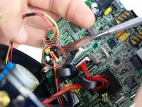
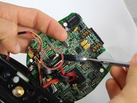
    4. Astak Mole Camera Head Replacement: step 9, image 1 of 1
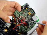
      • Separate the wire from CPU by cutting adhesive with metal spudger.

      • It is advised to reapply adhesive to wired connections during reassembly, and to re-attach wires to CPU to prevent disconnection and loose wires inside device.

      • Be careful not to damage the CPU in the process. This is not a wired connection.

      Ask FixBot

      Add Comment

Conclusion

To reassemble your device, follow these instructions in reverse order.

Cancel: I did not complete this guide.

Bryan

Member since: 09/15/16

104 Reputation

1 Guide authored

Team

USF Tampa, Team 2-2, Blackwell Fall 2016 Member of USF Tampa, Team 2-2, Blackwell Fall 2016

USFT-BLACKWELL-F16S2G2

4 Members

72 Guides authored

0 Guide Comments

Add Comment

View Statistics:

Past 24 Hours: 2

Past 7 Days: 12

Past 30 Days: 94

All Time: 1,071