Free Shipping on Domestic Orders $75+

Accessing Logicboard

Views: 2.2K

View statistics:

Past 24 Hours:
3
Past 7 Days:
18
Past 30 Days:
114
All Time:
2,195
Comments: 0

No one has left comments on this guide. Will you be first?

Go to guide comments
Completed: 0

No one has marked this guide "completed." Will you be the first?

Favorites: 0

No one has favorited (and subscribed to) this guide. Will you be the first?

Time Required: 7 minutes
Difficulty: Moderate
Accessing Logicboard

Introduction

Go to step 1 ↓

In this guide you will learn how to remove the SD card circuit board to access the logic board. To access the logic board, you will need to unsolder two leads. For soldering instructions, please refer to steps 1 through 6 of this soldering guide.

What you need

Tools

    1. Accessing Logicboard, Front and Back Cover: step 1, image 1 of 2 Accessing Logicboard, Front and Back Cover: step 1, image 2 of 2
      • Remove the following screws:

      • Two silver 3.15mm Phillips #00 screws on the right side of the camera

      • Two silver 2.08mm Phillips #00 screws on the left side of the camera

      Ask FixBot

      Add Comment

    2. Accessing Logicboard: step 2, image 1 of 1
      • Remove the two indicated screws on the bottom of the camera:

      • The screw circled in red is a longer silver 3.15mm Phillips #00 screw

      • The screw circled in blue is a shorter silver 2.25mm Phillips #00 screw

      Ask FixBot

      Add Comment

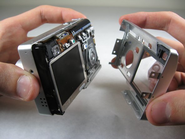
    3. Accessing Logicboard: step 3, image 1 of 2 Accessing Logicboard: step 3, image 2 of 2
      • Carefully pull the back of casing away from the front.

      Ask FixBot

      Add Comment

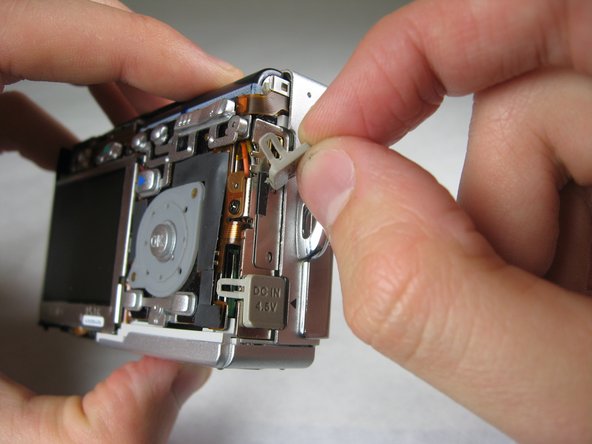
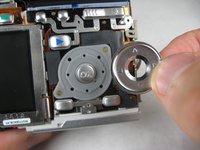
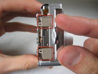
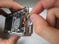
    4. Accessing Logicboard: step 4, image 1 of 3 Accessing Logicboard: step 4, image 2 of 3 Accessing Logicboard: step 4, image 3 of 3
      • After removing the back cover, several things must be removed.

      • Silver donut-shaped button will fall off. Place separately. Remove the plug covers on the right side of camera, labeled “PC/AV” and “DC IN 4.5V”.

      Ask FixBot

      Add Comment

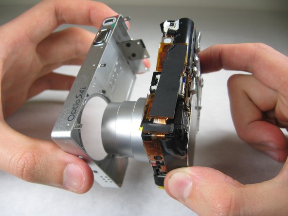
    5. Accessing Logicboard: step 5, image 1 of 2 Accessing Logicboard: step 5, image 2 of 2
      • To remove the front cover, gently hold the inside structure of the camera and slowly pull the front cover off.

      Ask FixBot

      Add Comment

    1. Accessing Logicboard, Logicboard: step 6, image 1 of 2 Accessing Logicboard, Logicboard: step 6, image 2 of 2
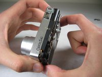
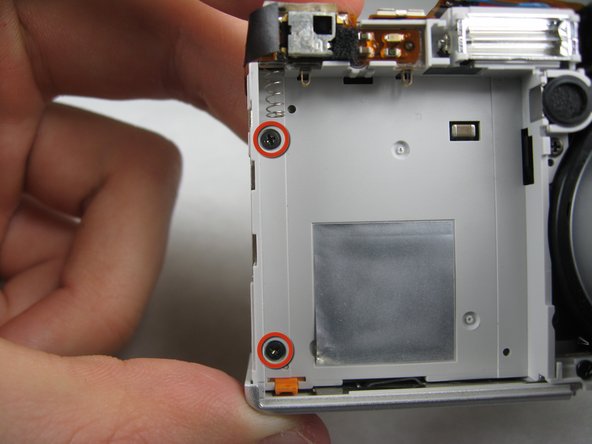
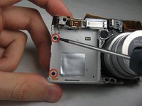
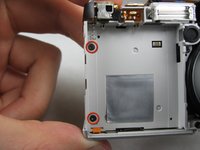
      • On the front of the camera, in battery case, remove screws indicated:

      • Two black 2.05mm Phillips #00 screws

      Ask FixBot

      Add Comment

    2. Accessing Logicboard: step 7, image 1 of 2 Accessing Logicboard: step 7, image 2 of 2
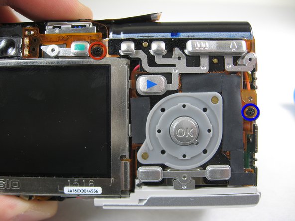
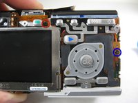
      • Flip the camera over to the backside and remove screws indicated:

      • The screw circled in red is a longer black 3.00mm Phillips #00 screw

      • The screw circled in blue is a shorter black 2.00mm Phillips #00 screw

      Ask FixBot

      Add Comment

    3. Accessing Logicboard: step 8, image 1 of 1
      • Pull the cover plate off for the two power cord jacks.

      Ask FixBot

      Add Comment

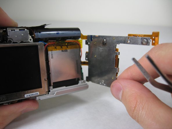
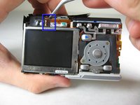
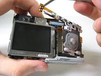
    4. Accessing Logicboard: step 9, image 1 of 3 Accessing Logicboard: step 9, image 2 of 3 Accessing Logicboard: step 9, image 3 of 3
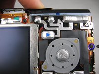
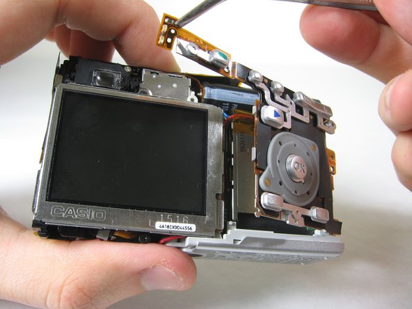
      • Cautiously and gently pull up the control board at the upper left corner, next to the viewfinder.

      Ask FixBot

      Add Comment

    5. Accessing Logicboard: step 10, image 1 of 1
      • Remove the orange tape on top of the SD cardholder.

      Ask FixBot

      Add Comment

    6. Accessing Logicboard: step 11, image 1 of 1
      • Open the battery cover.

      Ask FixBot

      Add Comment

    7. Accessing Logicboard: step 12, image 1 of 2 Accessing Logicboard: step 12, image 2 of 2
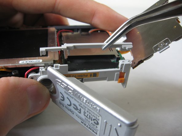
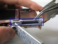
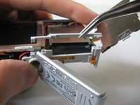
      • Lift the indicated plastic piece off.

      Ask FixBot

      Add Comment

    8. Accessing Logicboard: step 13, image 1 of 2 Accessing Logicboard: step 13, image 2 of 2
      • Remove screws indicated:

      • Two black 4.80mm Phillips #00 screws

      Ask FixBot

      Add Comment

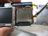
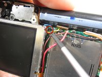
    9. Accessing Logicboard: step 14, image 1 of 1
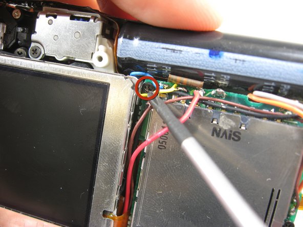
      • Unsolder points indicated.

      • Please refer to steps 1 through 6 of the Ifixit soldering guide to unsolder these leads.

      Ask FixBot

      Add Comment

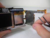
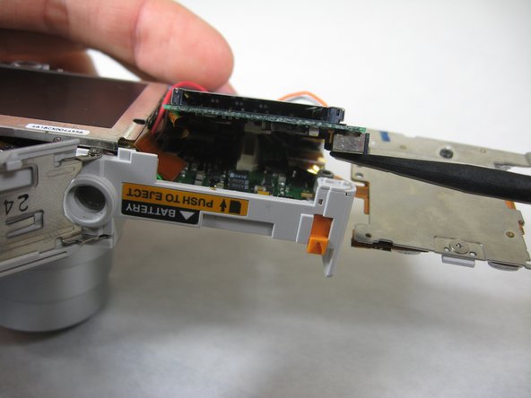
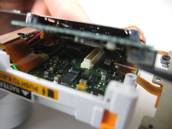
    10. Accessing Logicboard: step 15, image 1 of 3 Accessing Logicboard: step 15, image 2 of 3 Accessing Logicboard: step 15, image 3 of 3
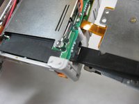
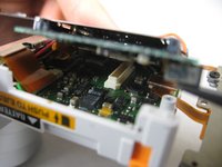
      • Carefully lift up SD cardholder to reveal logicboard.

      Ask FixBot

      Add Comment

Conclusion

To reassemble your device, follow these instructions in reverse order.

Cancel: I did not complete this guide.

Nicole Wong

Member since: 01/30/11

371 Reputation

3 Guides authored

Team

Cal Poly, Team 4-29, Regan Winter 2011 Member of Cal Poly, Team 4-29, Regan Winter 2011

CPSU-REGAN-W11S4G29

3 Members

60 Guides authored

0 Guide Comments

Add Comment

View Statistics:

Past 24 Hours: 3

Past 7 Days: 18

Past 30 Days: 114

All Time: 2,195