This translation was generated by a machine and has not been reviewed by a person yet. Speak this language? Review it.
-
-
-
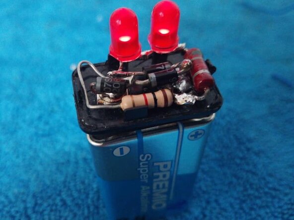
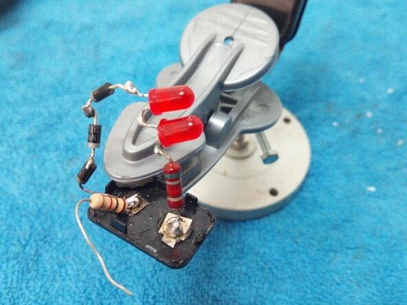
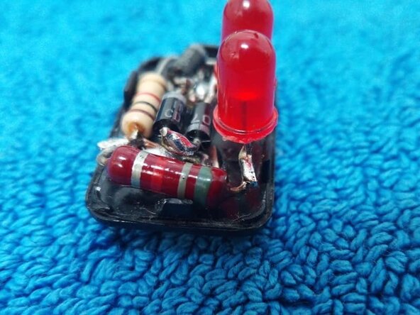
Another model of a 9V battery tester, in this case using 2 LED diodes and 3 standard rectifier diodes; personally, I like the other 2 testers better, but this one works too.
-
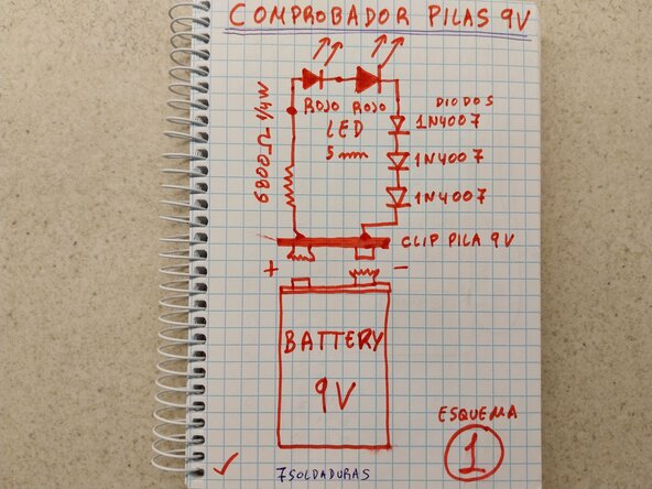
View of the design and simple electrical schematic; the improved design includes a discharge resistor between the battery terminals.
-
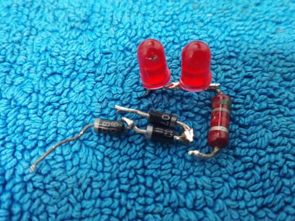
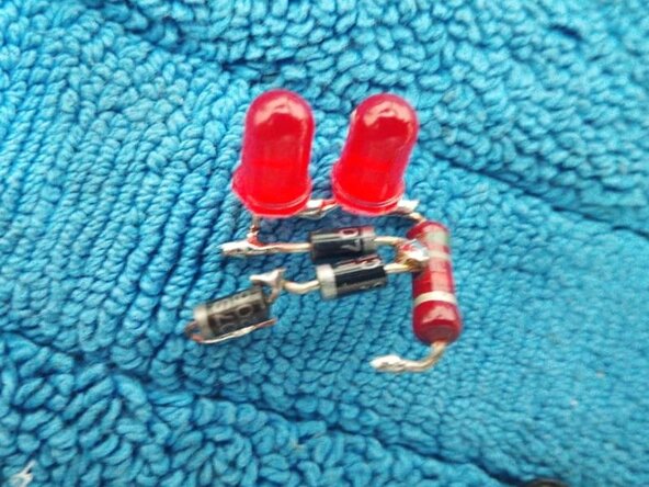
1 Resistance of 6800 ohms 1/4W or 1/2W, 2 Red 5 mm LEDs, 3 1N4007 rectifier diodes, 1 9V battery clip, quick-drying 2-component glue.
 Ask FixBot
-
-
-
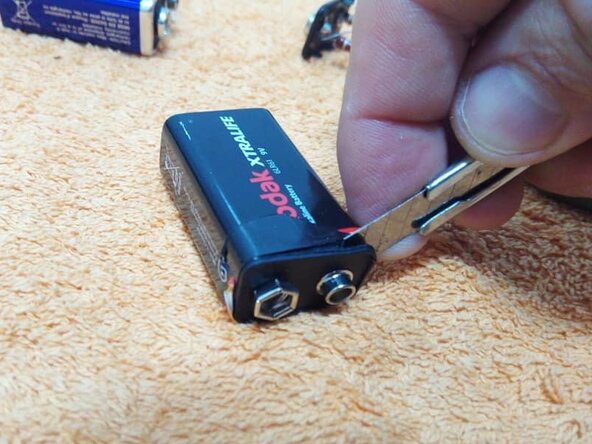
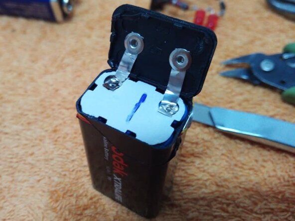
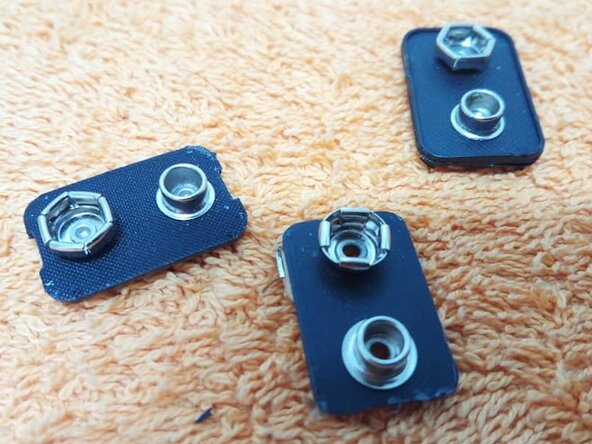
The mounting base is a 9 V battery clip that we will obtain from a 9V battery; it is a great clip that we will use as a base for this assembly.
-
-
-
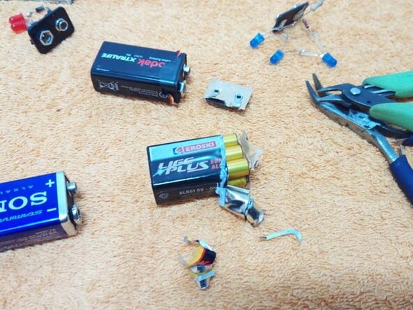
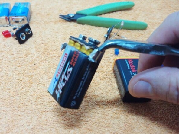
Depending on how the battery is constructed, we will obtain the clip in one way or another; in this case, by rolling the metal casing around the needle-nose pliers.
-
-
-
-
In the assembly phase, we will perform the soldering between diodes and with the resistance, then soldering the 3 rectifier diodes.
-
Video with the previous assembly improved by adding a discharge resistance.
-
-
-
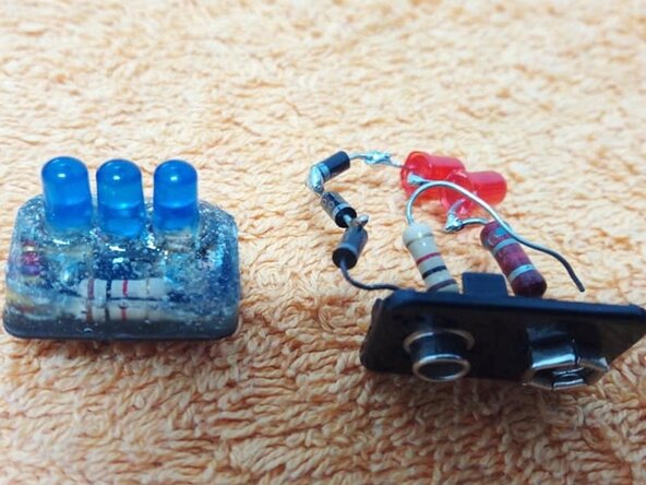
Assembly views before flattening everything into the clip to apply a layer of quick-drying 2-component glue, compared with the 3-LED version.
-
-
-
View of the flattened components, correctly isolated from one another, before applying the 2-component glue that will harden them.
-
-
-
Final view before applying the glue; to apply this, we will wrap the 4 sides of the clip with electrical tape and fill the center until all components are completely covered.
-
END of the Guide:
-
Other guides in this series: Electronics Skills
-
-














To reassemble your device, follow these instructions in reverse order.
Cancel: I did not complete this guide.
2 other people completed this guide.

