422TTL modification for Bench DC Power

warrenjrose and one other contributor
Last updated on Dec 11, 2024
Views: 214
View statistics:
- Past 24 Hours:
- 0
- Past 7 Days:
- 9
- Past 30 Days:
- 59
- All Time:
- 214
Comments: 0
No one has left comments on this guide. Will you be first?
Go to guide commentsCompleted: 0 1
No one has marked this guide "completed." Will you be the first?
1 person has marked this guide "completed." It's you — great job!
Favorites: 0 1
No one has favorited (and subscribed to) this guide. Will you be the first?
1 person has favorited (and subscribed to) this guide — and that's you!
Community-Contributed Guide
An awesome member of our community made this guide. It was not created by iFixit staff.
Introduction
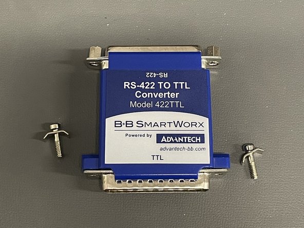
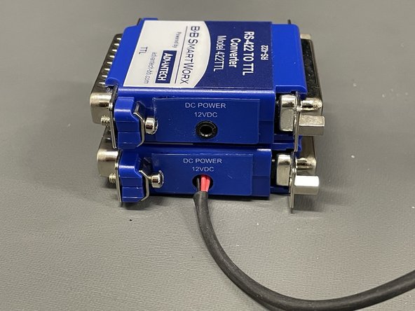
Go to step 1 ↓The Advantech 422TTL is used to convert a TTL signal, into a differential 422 signal. However, when using the recommended power supply, the output on the RS-422 side is absolute garbage due to the cheap switching power supply injecting noise. We were converting PPS.
We fixed this by using a bench top 12VDC power supply for nice clean power. This guide will document that modification.
-
-
-
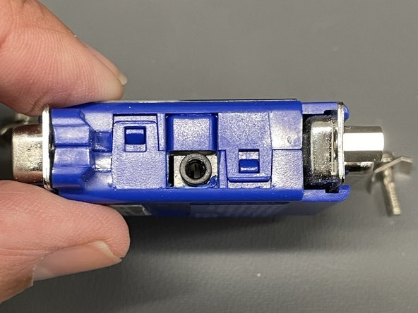
Remove side sticker (DC Power 12VDC)
-
Remove hardware (Screws and metal tabs)
-
Carefully lift 4 tabs (2 per side) to split unit into two halves.
 Ask FixBot
-
-
-
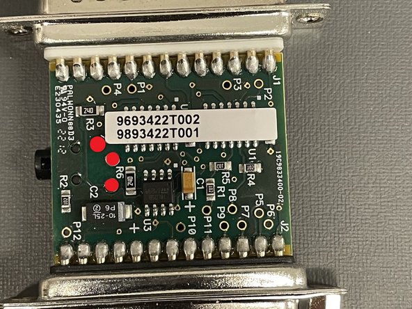
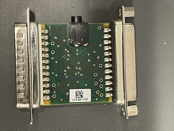
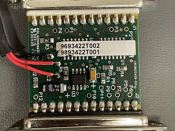
Remove the PCB from housing, examining where the headphone style power adapter attaches.
-
Desolder and remove the power adapter.
-
-
-
-
Positive (red) and negative (black) power lines should attach where the socket was removed.
-
-





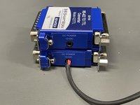
To reassemble your device, follow these instructions in reverse order.